
Composite Connection For A Wind Turbine Tower Structure

Active Publication Date: 2012-06-28
GE RENEWABLE TECH WIND BV
View PDF3 Cites 2 Cited by
  • Summary
  • Abstract
  • Description
  • Claims
  • Application Information

AI Technical Summary

Benefits of technology

[0012]The tower section of the invention comprises at least two shell segments that can be made of metal, such as steel. The tower section of the invention may be cylindrical or frustoconical in shape, in the latter case being arranged such that diameter increases towards the base in order to enhance strength and to save materials.
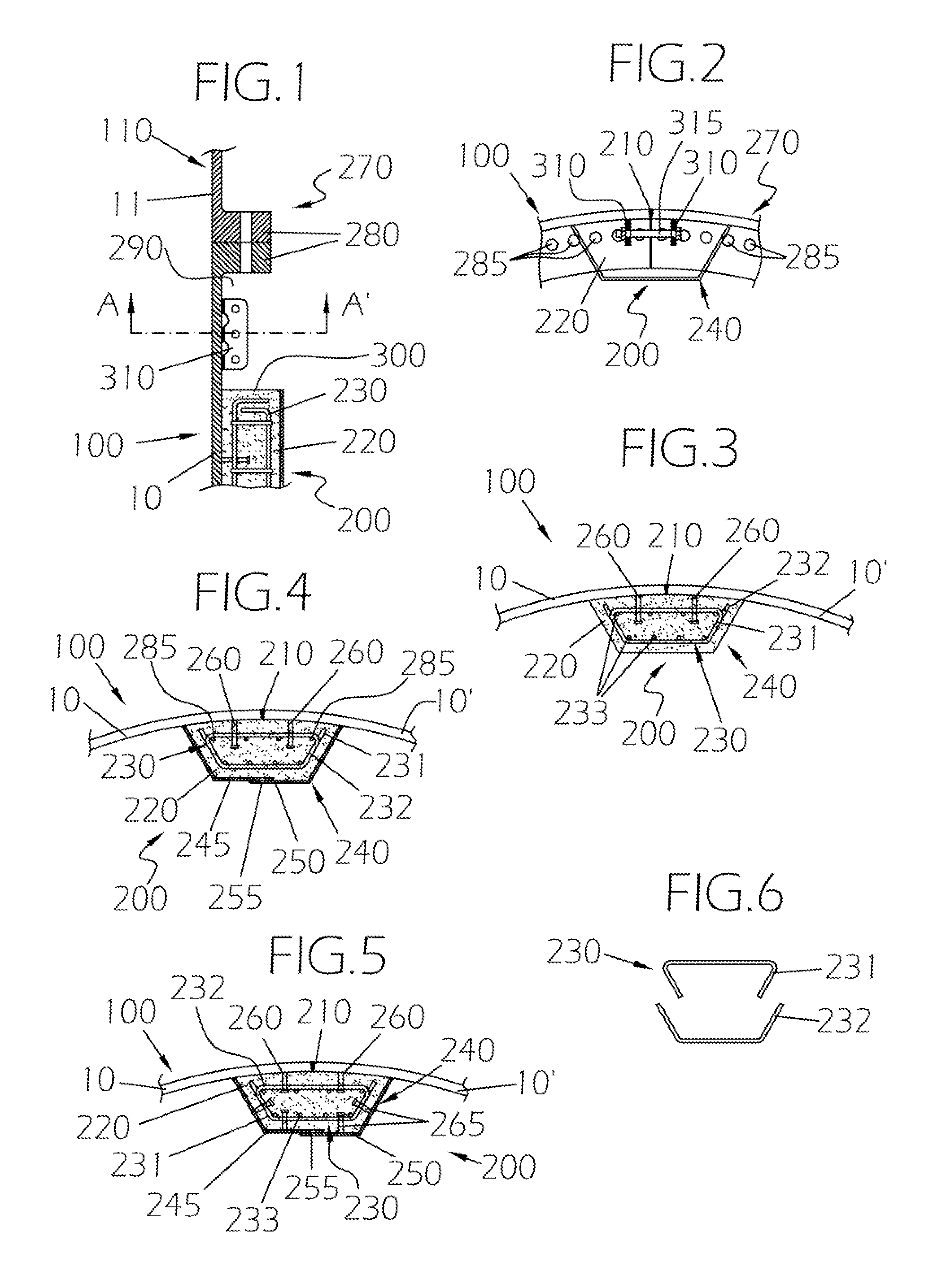
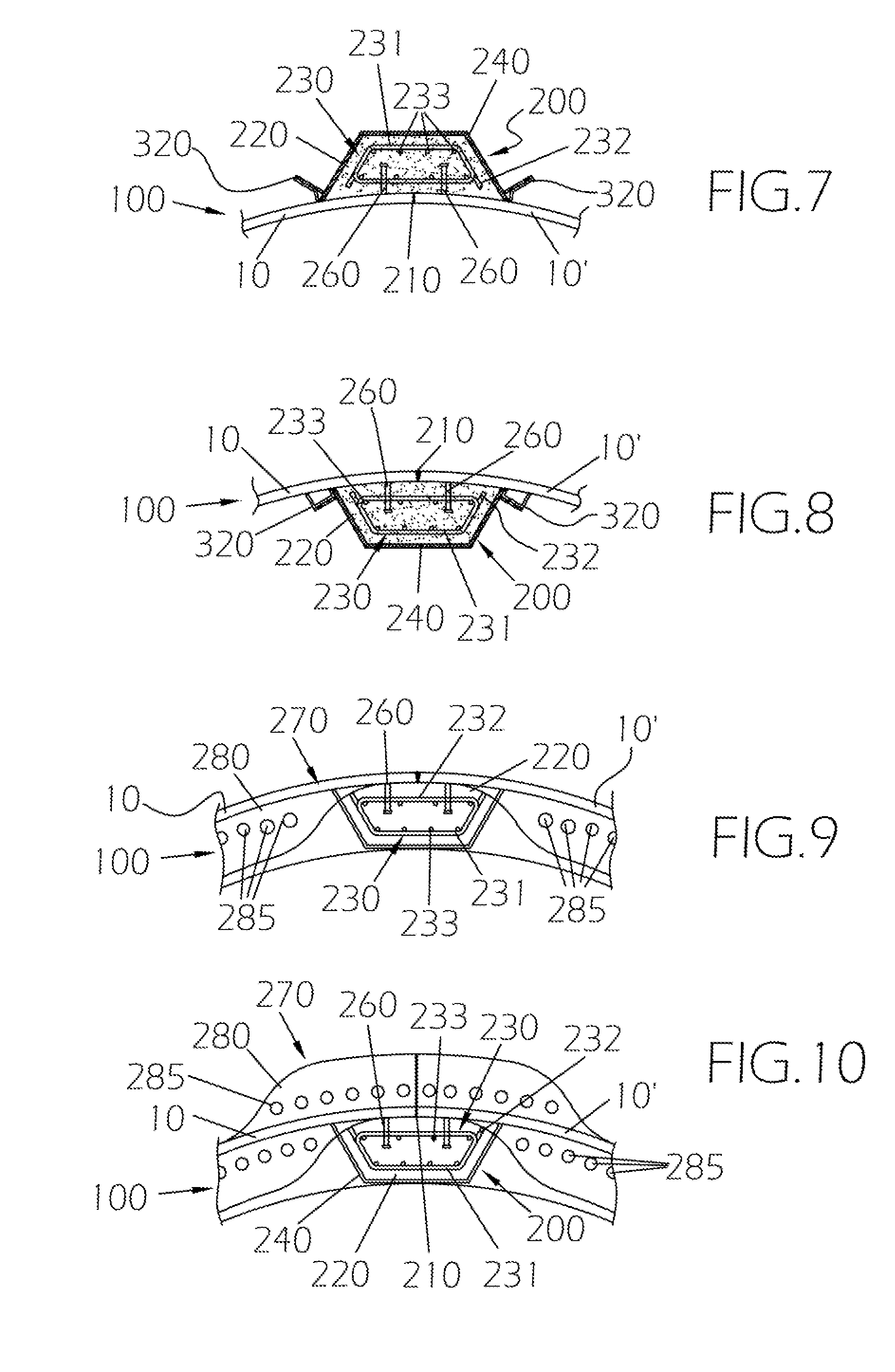
[0016]At least one of the shell segments may be provided with shear connectors (e.g. welded to the shell segments) protruding therefrom and embedded in the column of concrete in the assembled condition. In this way, within the closed space defined by the formwork, shear connectors along with the corresponding steel reinforcement are embedded within concrete when in said assembled condition. Shear connectors and steel reinforcement serve the purpose of ensuring shear strength between the shell segments.
[0017]In one embodiment, the formwork may be integral with at least one of the shell segments (lost formwork). In other embodiment, the formwork may be removable from at least one of the shell segments. In this case, a reduction of costs can be achieved since the formwork may be reused for different wind turbine towers. Furthermore imperfections in the column of concrete can be repaired after formwork removal.
[0020]The invention further provides a method for building a tower section for a wind turbine tower structure. The method comprises the steps of providing at least two of such shell segments, placing the shell segments such that a substantially hollow structure is defined and forming a column of concrete arranged overlapping at least part of a joint between adjacent shell segments. Column formation may be carried out, for example, by pouring concrete into the closed volume defined by the formwork and allowing concrete to set for structurally fixing the tower shell segments. Once the tower section is formed (by joining adjacent shell segments) a further step may be performed of mutually joining two adjacent tower sections one above the other through the use of second connecting means, for example through an arc flat bolted flange. The provision of the second connecting means allow several tower sections to be joined one above the other and flange stiffness in the gap portion to be increased.
[0022]The main advantages of the invention are that there is no need for the pretension of a large number of bolts to be regularly controlled throughout the tower structure service live. This results in lower costs involved. In addition, maintenance costs are further reduced since no access is needed along the length of the joint for maintenance operations as occurs in the prior art tower structures formed of several shell segments (which used vertical flanges and long vertical welded lines to connect flanges to shell segments).
[0023]Additional advantages of the invention are that the use of columns of concrete allows dimensional tolerances to be best accommodated as well as achieving a reliable joint sealing since the column of concrete prevents joint sealing material from being degraded.

Problems solved by technology

In practice, however, tower dimensions are limited (up to 4.5 m in diameter) due, for example, to transport requirements.
Such a limitation results in a non-linear increase of tower costs as the wall thickness is increased and hence the tower design obtained is not optimal.
Furthermore, other limitations are involved in tower designs such as tower wall thickness due to manufacturing processes.
The main disadvantages with these solutions relate to high manufacturing, installation and maintenance costs due to the large number of pre-stressed bolts required at vertical flange connections.

Method used


Image

  • Composite Connection For A Wind Turbine Tower Structure
  • Composite Connection For A Wind Turbine Tower Structure
  • Composite Connection For A Wind Turbine Tower Structure

Examples


Embodiment Construction

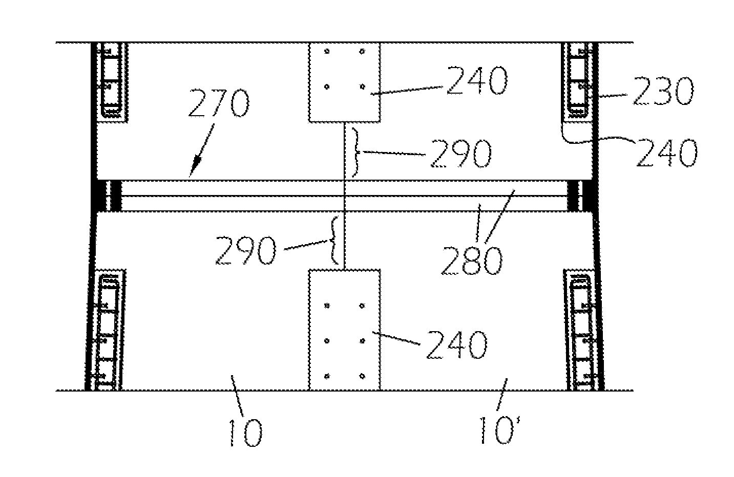
[0036]A tower structure (a substantially hollow structure) comprises a plurality of tower sections 100, 110. Two of them are generally depicted in FIG. 1 for purposes of clarity. In use, the tower sections 100, 110 are arranged on one another for forming a wind turbine tower structure. A tower section 100 is formed with a plurality of shell segments 10, 10′. Likewise, the contiguous tower section 110 fixed to said other tower section 100 is formed with corresponding shell segments, only one of which is shown and designed at 11. Each shell segment 10, 10′, 11 consists of a unitary curved plate made of metal such as steel.

[0037]FIG. 1, for example, shows part of two shell segments 10, 11 of different tower sections 100, 110 with one section arranged above the other and defining a cylindrical or frustoconical tower structure depending on the geometry of the shell segments 10, 10′, 11 and therefore that of tower section formed.

[0038]First connecting means 200 are provided for mutually j...


PUM


Abstract

A tower section for a wind turbine tower structure comprises at least two shell segments defining, in an assembled condition, a substantially hollow structure, and including first connecting means for mutually joining two adjacent shell segments along a joint, which comprise a column of concrete arranged overlapping at least part of the joint between adjacent shell segments. A method for building a tower section for a wind turbine tower structure and a wind turbine comprising a nacelle having rotatable blades and a vertical tower made of at least one of such tower sections are further provided.

Description

CROSS-REFERENCE TO RELATED APPLICATIONS[0001]This application claims priority to PCT Application No. PCT / EP2010 / 056760 entitled “COMPOSITE CONNECTION FOR A WIND TURBINE TOWER STRUCTURE”, filed May 18, 2010, which claims priority to European Application No. 09160871.1 entitled “COMPOSITE CONNECTION FOR A WIND TURBINE TOWER STRUCTURE”, filed May 21, 2009, the disclosure of each is hereby incorporated by reference as if set forth in its entirety herein.STATEMENT REGARDING FEDERALLY SPONSORED RESEARCH OR DEVELOPMENT[0002]Not applicable.TECHNICAL FIELD[0003]The present invention relates to a tower section for a wind turbine tower structure. The invention is particularly useful for, but not limited to, large wind turbine towers and, in general, for tubular structures which have to withstand high loads.[0004]A tower section according to the invention comprises two or more shell segments. In an assembled condition, the shell segments define a substantially hollow structure which will be ref...

Claims


Application Information

Patent Timeline
IPC IPC(8): E04H12/00E04B1/38E04G13/02E04G21/02E04B2/34
CPCE04H12/08E04H12/12Y02E10/728F05B2240/912F05B2230/60
Inventor PUIGCORBE PUNZANO, JORDIFISAS CAMANES, ALBERTGONZALEZ DEL EGIDO, ALBERTOGARCIA GOMEZ, N RIA
Owner GE RENEWABLE TECH WIND BV
Learn More