Control sysytem for motor-driven lawnmower vehicle

a technology of control system and lawnmower, which is applied in the direction of non-deflectable wheel steering, electric devices, engine-driven generators, etc., can solve the problems of rear wheels and front wheels slipping with respect to the ground surface, insufficient traveling driving force of left and right rear wheels as main drive wheels, and insufficient traveling driving for

Inactive Publication Date: 2012-06-28
KANZAKI KOKYUKOKI MFG
View PDF1 Cites 70 Cited by
  • Summary
  • Abstract
  • Description
  • Claims
  • Application Information

AI Technical Summary

Benefits of technology

[0026]At least one embodiment of a control system for a motor-driven lawnmower vehicle according to the present invention is a control system for an engineless, motor-driven lawnmower vehicle. The control system includes a plurality of electric motors and a plurality of controllers. Among the plurality of electric motors, at least one of the electric motors is an electric drive motor connected to a drive wheel of the motor-driven lawnmower vehicle in a manner capable of transmitting motive power. Among the other electric motors, at least one electric motor is a mower-related electric motor connected to a lawnmower rotary tool in a manner capable of transmitting moti

Problems solved by technology

For example, when the ground surface is uneven or when the surface is sloped, there are cases when the traveling driving force of the left and right rear wheels as main drive wheels is insufficient.
Thus, in a riding lawnmower according to the related art, depending on the ground surface conditions such as a sloping surface, a case may arise in which the traveling driving force is insufficient.
In contrast, however, in the case of turning while traveling over a sloping surface, if the aforementioned traveling driving force is insufficient, a case may arise in which the rear wheels and the front wheels slip with respect to the ground surface and the turn itself can not be executed adequately.
Further, if a turn is executed while slipping on the ground surface, there is a risk that the planting condition of the lawn or the ground surface state will be damaged.
Even when it can be assumed that a traveling driving force is applied to the front wheels to drive the front wheels and rear wheels at a uniform speed, for example, when executing a turn, a difference will arise between the turning speed of the front wheels and the turning speed of the rear wheels due to the turn center position, and it will not be possible to turn smoothly.
As a result of the turn not being performed smoothly, there is a risk that the front wheels or the rear wheels will slip on the lawn and damage the planting condition of the lawn or the ground surface condition.
However, depending on the state of the wheel on one side, the planting condition of the lawn may be damaged by the turning of the wheel on one side as the turn center position.
Further, on sloping ground, if the turning radius is too small the vehicle itself may enter an unstable state due to a shift in the center of gravity of the riding lawnmower.
Thus, depending on the nature of the lawn mowing task, there are times when delicate control is required when traveling or turning.
This type of delicate control is not adequately provided for according to the related art.
In a conventional riding lawnmower comprising caster wheels and main drive wheels in which the caster wheels are allowed to steer freely, there is a possibility that trouble will occur on a sloping surface.
For example, as a first kind of trouble, when the operator attempts to turn the vehicle while traveling over a sloping surface, there is a possibility that a force acting on the caster wheels in a downward direction produced as a result of gravity acting

Method used


Image

  • Control sysytem for motor-driven lawnmower vehicle
  • Control sysytem for motor-driven lawnmower vehicle
  • Control sysytem for motor-driven lawnmower vehicle

Examples


first embodiment

[0110]Hereunder, a first embodiment of the present invention relating to a first aspect and a second aspect of the present invention is described in detail while referencing the drawings. Although in the following description a four-wheel drive type apparatus having left and right rear wheels as main drive wheels and left and right front wheels as steering control wheels that are each independently provided with an electric rotary machine is described as an example riding lawnmower, this embodiment may also be applied to riding lawnmower of a three-wheel drive type having one wheel as a steering control wheel, or the like.

[0111]Further, although in the following an example is described wherein an electric rotary machine is used as a driving source of the riding lawnmower, as a driving source of the left and right rear wheels, a driving source of the steering control wheels, and as a driving source of a lawnmower blade, a driving source other than an electric rotary machine may be us...

example 1

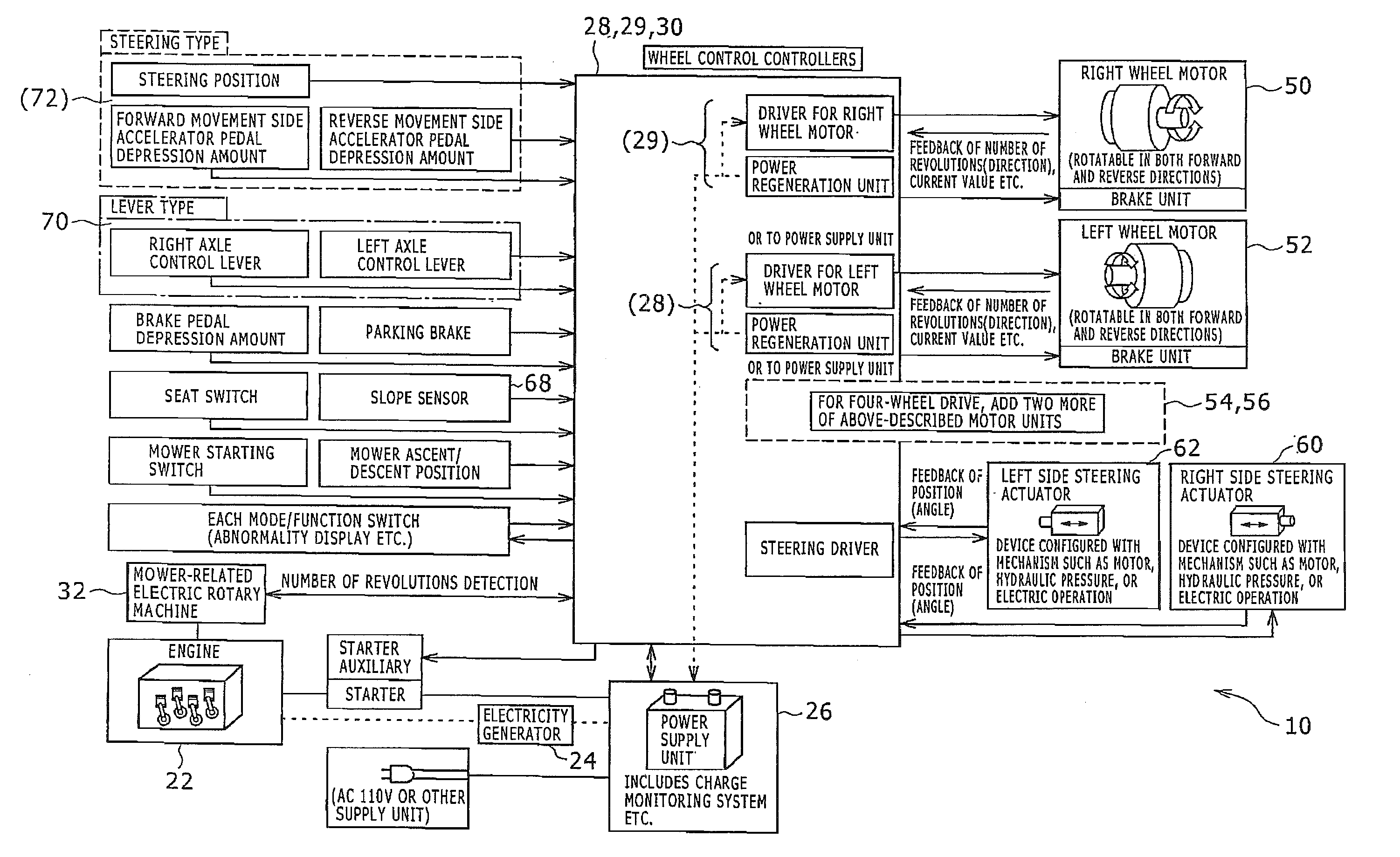
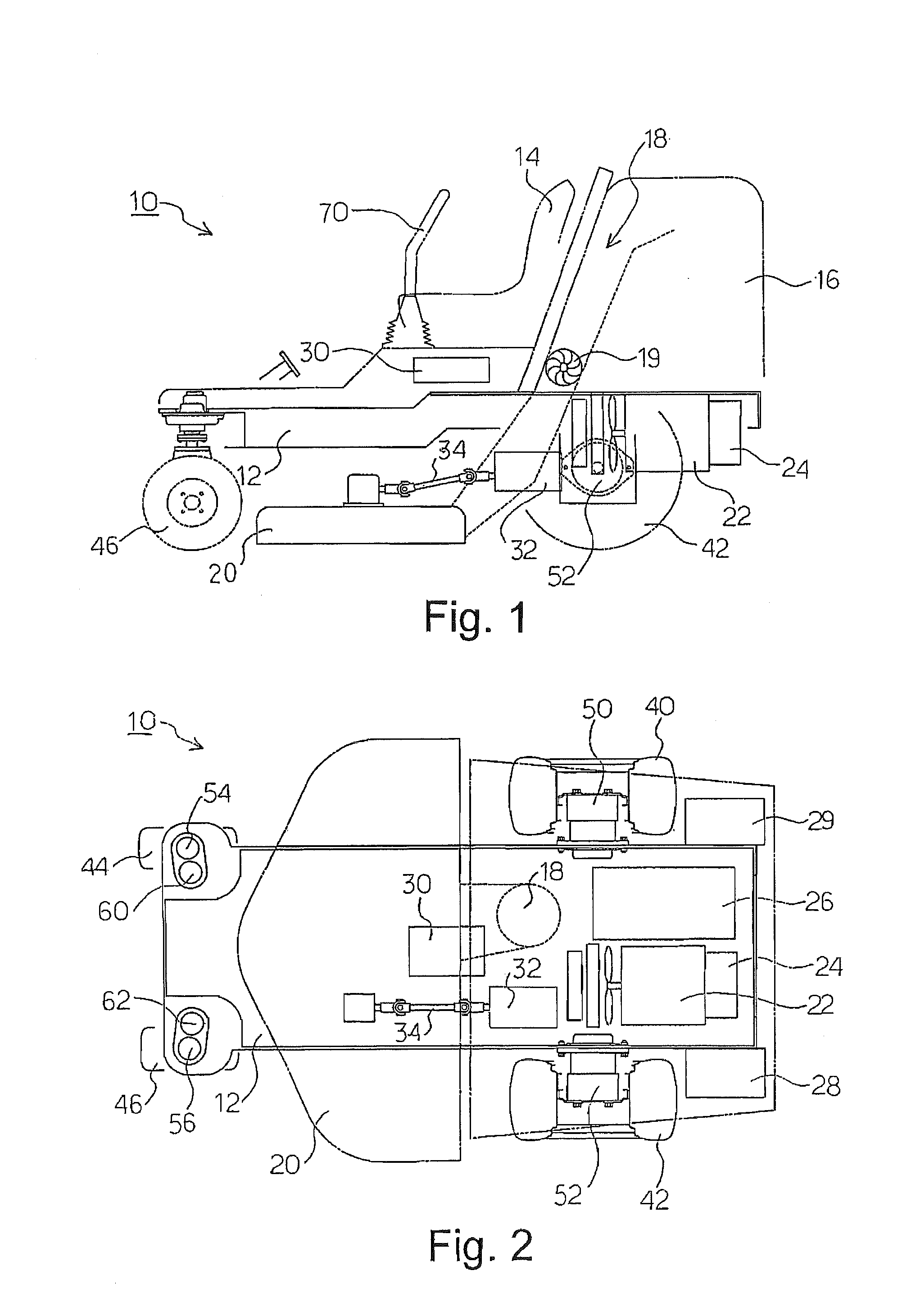
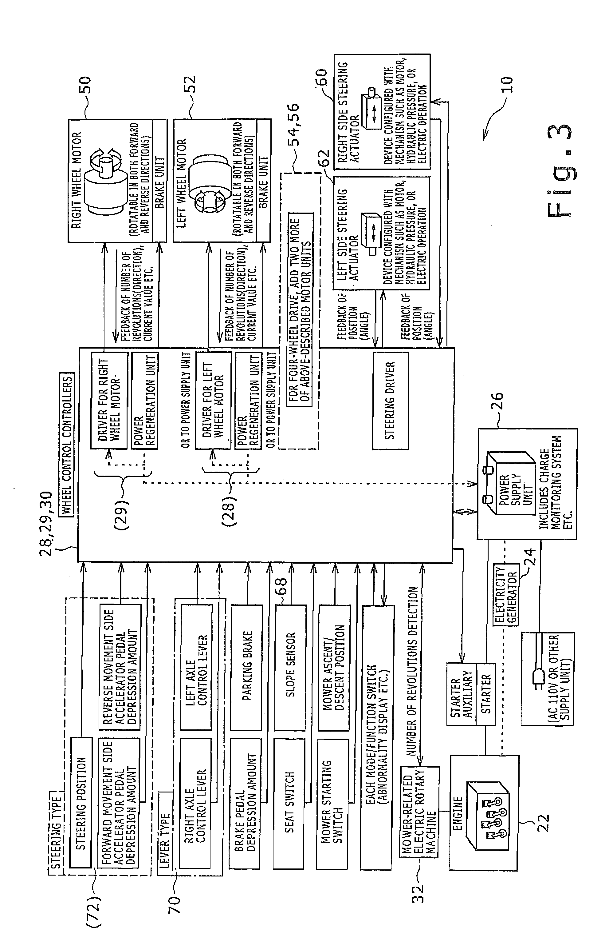
[0116]FIG. 1 is a side view of a riding lawnmower 10, and FIG. 2 is an abbreviated top view that illustrates components on a main frame 12 in the riding lawnmower 10. FIG. 3 is a block diagram that relates to electrical system components in the riding lawnmower 10. First, the disposition of each component is described centering on the main frame 12 using FIG. 1 and FIG. 2. Thereafter, the details of each component are described using FIG. 3.

[0117]As shown in FIG. 1 and FIG. 2, the riding lawnmower 10 is a self-propelled off-road vehicle suited to lawn mowing in which components such as left and right wheels 40 and 42 as main drive wheels, left and right caster wheels 44 and 46 as steering control wheels, a mower deck 20 provided with a lawnmower blade as a lawnmower rotary tool, and a seat 14 on which an operator sits and performs steering for lawn mowing work are attached to the main frame 12.

[0118]The main frame 12 forms the skeleton of the riding lawnmower 10, and is configured a...

example 2

[0152]FIG. 8 is a block diagram regarding a portion relating to a turn function in a case in which the riding lawnmower 10 comprises a two lever-type operator. In this connection, the example section will be described again with respect to a case in which the riding lawnmower comprises a steering operator. Hereunder, the same reference numerals are assigned to components that are the same as components described in FIG. 1 to FIG. 3 and a detailed description thereof will not be repeated. In the following description the reference numerals shown in FIG. 1 to FIG. 3 are used. The portion corresponding to the controllers 28, 29, and 30 in FIG. 3 is represented as a control section 100 in FIG. 8. In the control section 100, the turn drive module 112 corresponds to controllers 28 and 29 including a driver circuit portion for each electric rotary machine, and the other portions and a memory section 102 connected to the control section 100 correspond to the controller 30 including the cont...


PUM


Abstract

A control system for an engineless, motor-driven lawnmower vehicle includes electric motors and controllers. At least one of the electric motors is an electric drive motor connected to a drive wheel of the lawnmower vehicle to enable transmission of motive power. At least one other electric motor is a mower-related electric motor connected to a lawnmower rotary tool to enable transmission of motive power. At least one of the controllers is a drive wheel controller which includes a drive wheel driver and which controls operation of the electric drive motor in response to a signal from at least one operator sensor for detecting an operation amount of at least one operator. At least one controller controls to activate or stop the mower-related electric motor. At least one controller is connected to the drive wheel controller and transmits a control signal thereto in response to a signal from the operator sensor.

Description

PRIORITY INFORMATION[0001]The present application is a continuation-in-part application filed from U.S. patent application Ser. No. 12 / 014,579 filed on Jan. 15, 2008, which is incorporated herein by reference in its entirety. U.S. Ser. No. 12 / 014,579 claims priority from Japanese Patent Application No. 2007-006219, Japanese Patent Application No. 2007-006220, and Japanese Patent Application No. 2007-006221, each filed on Jan. 15, 2007.BACKGROUND[0002]1. Technical Field[0003]The present invention relates to a control system for a motor-driven lawnmower vehicle.[0004]2. Related Art[0005]With regard to the present invention relating to the first aspect and the second aspect, an apparatus for mowing grass such as lawn grass that is planted on the ground surface of a garden or the like is generally referred to as a “lawnmower”, although naturally such apparatuses are also used to mow grasses other than lawn grass. Types of lawnmowers include handheld lawnmowers and wheel movement-type la...

Claims


Application Information

Patent Timeline
IPC IPC(8): A01D69/02A01D75/18A01D34/00
CPCA01D34/64Y02T10/7275A01D69/02B60K7/0007B60K17/043B60K2007/0061B60K2007/0076B60K2007/0092B62D11/003B62D11/04B62D11/24B60L11/18B60L15/20B60L2200/40Y02T10/7005Y02T10/648A01D34/78B60L1/003B60L3/106B60L8/003B60L15/2009B60L15/2036B60L15/2054B60L2210/10B60L2210/40B60L2220/44B60L2220/46B60L2240/12B60L2240/24B60L2240/30B60L2240/421B60L2240/423B60L2240/465B60L2240/486B60L2240/642B60L2250/16B60L2250/22B60L2250/24B60L2250/26B60L2260/26Y02T90/16Y02T10/7072Y02T90/14B60L53/14B60L50/62B60L50/16B60L58/21B60L50/66B60L58/40Y02T10/62Y02T10/64Y02T10/70Y02T10/72Y02T90/12Y02T90/40A01D34/006
Inventor ISHII, NORIHIROSASAHARA, KENGOKOGA, KAZUNARIMATSUURA, JUNEBIHARA, TOMOYUKIMIZUKAWA, KATSUMOTOWANG, HONGKUN
Owner KANZAKI KOKYUKOKI MFG
Why Eureka
Try Eureka