Circuit board to be attached to support through thermoplastic staking

a technology of thermoplastic staking and circuit board, which is applied in the field of circuit boards, can solve the problems of increasing the production cost of the circuit board and the case body, and reducing the strength of fastening the circuit board to the case body. it is convenient to increase the total thickness of the printed layer, and achieves the effect of convenient increas

Inactive Publication Date: 2012-06-28
DENSO CORP
View PDF7 Cites 12 Cited by
  • Summary
  • Abstract
  • Description
  • Claims
  • Application Information

AI Technical Summary

Benefits of technology

[0008]It is therefore an object to provide an improved structure of a circuit board which is designed to ensure a high degree of strength in fastening the circuit board to a support such as a case body.
[0009]It is another object to provide an improved structure of a circuit board which facilitates the ease with which a failure in thermoplastic staking is visually inspected.

Problems solved by technology

When the circuit board coated with the moisture-proof material, as disclosed in the former publication, is secured to the case body using the thermoplastic staking technique, as taught in the latter publication, the problem is encountered in that the strength of fastening the circuit board to the case body is reduced.
For instance, when applied over the circuit board, the moisture-proof material may drip into the mounting hole, thereby resulting in a reduction in strength in fastening the circuit board to the case body.
The amount of the moisture-proof material dripping into the mounting hole may be decreased by increasing the size of the circuit board, but it will also require increasing the size of the case body, thus resulting in an increase in production cost of the circuit board and the case body.
The increase in size of the circuit board may also lead to deformation or breakage thereof.
It is, therefore, difficult to visually inspect a failure in the thermoplastic staking arising from misalignment of a staking punch or dimension tolerances of the mounting holes and the studs.
This permits the printed layer to be minimized in area, thus resulting in a decrease in production cost of the circuit board.

Method used


Image

  • Circuit board to be attached to support through thermoplastic staking
  • Circuit board to be attached to support through thermoplastic staking
  • Circuit board to be attached to support through thermoplastic staking

Examples


Embodiment Construction

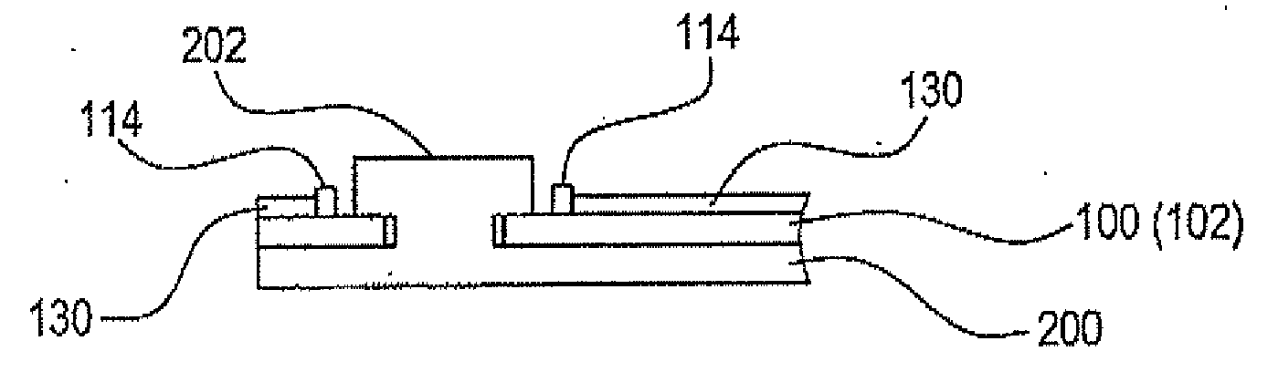
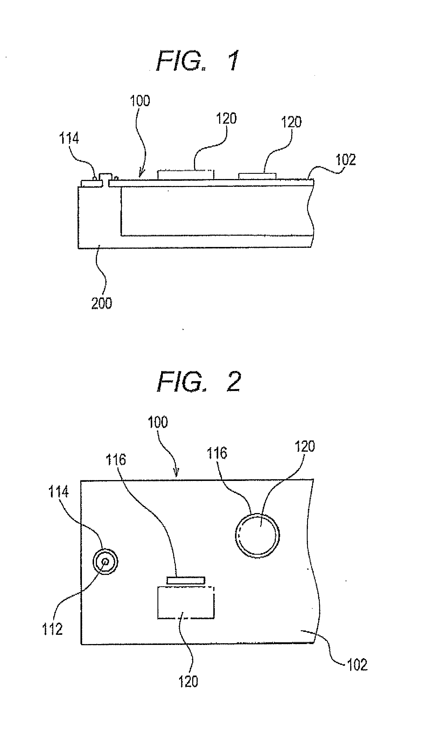
[0038]Referring to the drawings, wherein like reference numbers refer to like parts in several views, particularly to FIG. 1, there is shown a printed circuit assembly 100 which is secured to a case body 200 by means of thermoplastic staking (also called heat staking or riveting) according to an embodiment of the invention. FIG. 1 is a partially sectional view of the printed circuit assembly 100 attached to the case body 200. FIG. 2 is a plane view of FIG. 1.

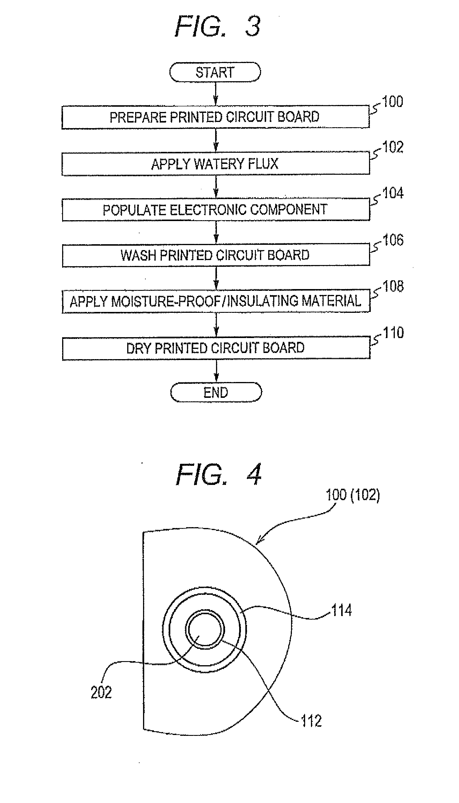
[0039]The printed circuit assembly 100 is equipped with a printed circuit board 102 which is fixed to the case body 200 (i.e., a support) using the thermoplastic staking technique. The printed circuit board 102 has mounting holes 112 (only one is shown for the brevity of illustration). The printed circuit assembly 100 also includes a printed mounting hole surrounding layer 112 formed around the mounting hole 112, and printed component marks 116 each of which represents the location on the printed circuit board 102 where an elect...


PUM


Abstract

A circuit board to be attached to a support such as a case body is provided. The circuit board has formed therein a mounting hole which is so designed as to permit a thermally deformable stud to protrude through the mounting hole and also to be thermoplastically staked to mount the board to the support. A layer is printed on the board by means of silk screen printing at a distance from the mounting hole. In a case where a moisture-proof and insulating material is applied over a surface of the board, the printed layer servers to block a flow of the moisture-proof and insulating material into the mounting hole. This avoids a reduction in strength of fastening the board to the support. The printed layer may also be used in visually inspecting a failure in thermoplastic staking to mount the board to the support.

Description

CROSS REFERENCE TO RELATED DOCUMENT[0001]The present application claims the benefit of priority of Japanese Patent Application No. 2010-286822 filed on Dec. 23, 2010, the disclosure of which is incorporated herein by reference.BACKGROUND OF THE INVENTION[0002]1 Technical Field[0003]This disclosure relates generally to a circuit board to be attached to a support such as a case body by means of that moplastic staking.[0004]2 Background Art[0005]Japanese Patent First Publication No. 8-32214 teaches a technique of applying a watery flux over the surface of a circuit board, soldering electronic components onto the circuit board, washing the circuit board to remove the flux, applying a moisture-proof material (also called a damp-proof material) onto the circuit board, and drying it. Japanese Patent First Publication No 2000-313346 discloses a circuit case in which a circuit board is secured to a synthetic resin-made case body by means of thermoplastic riveting or staking. Specifically, th...

Claims


Application Information

Patent Timeline
Patent Type & Authority Applications(United States)
IPC IPC(8): H05K1/02
CPCH05K3/0064H05K3/28H05K2201/09936H05K2201/09909H05K2201/09063
Inventor NAKANISHI, MASAYATANABE, YASUHITOWATANABE, HIDEMITSU
Owner DENSO CORP
Why Eureka
Try Eureka