Anode shroud for off-gas capture and removal from electrolytic oxide reduction system

Active Publication Date: 2012-06-28
GE HITACHI NUCLEAR ENERGY AMERICAS
View PDF3 Cites 4 Cited by
  • Summary
  • Abstract
  • Description
  • Claims
  • Application Information

AI Technical Summary

Benefits of technology

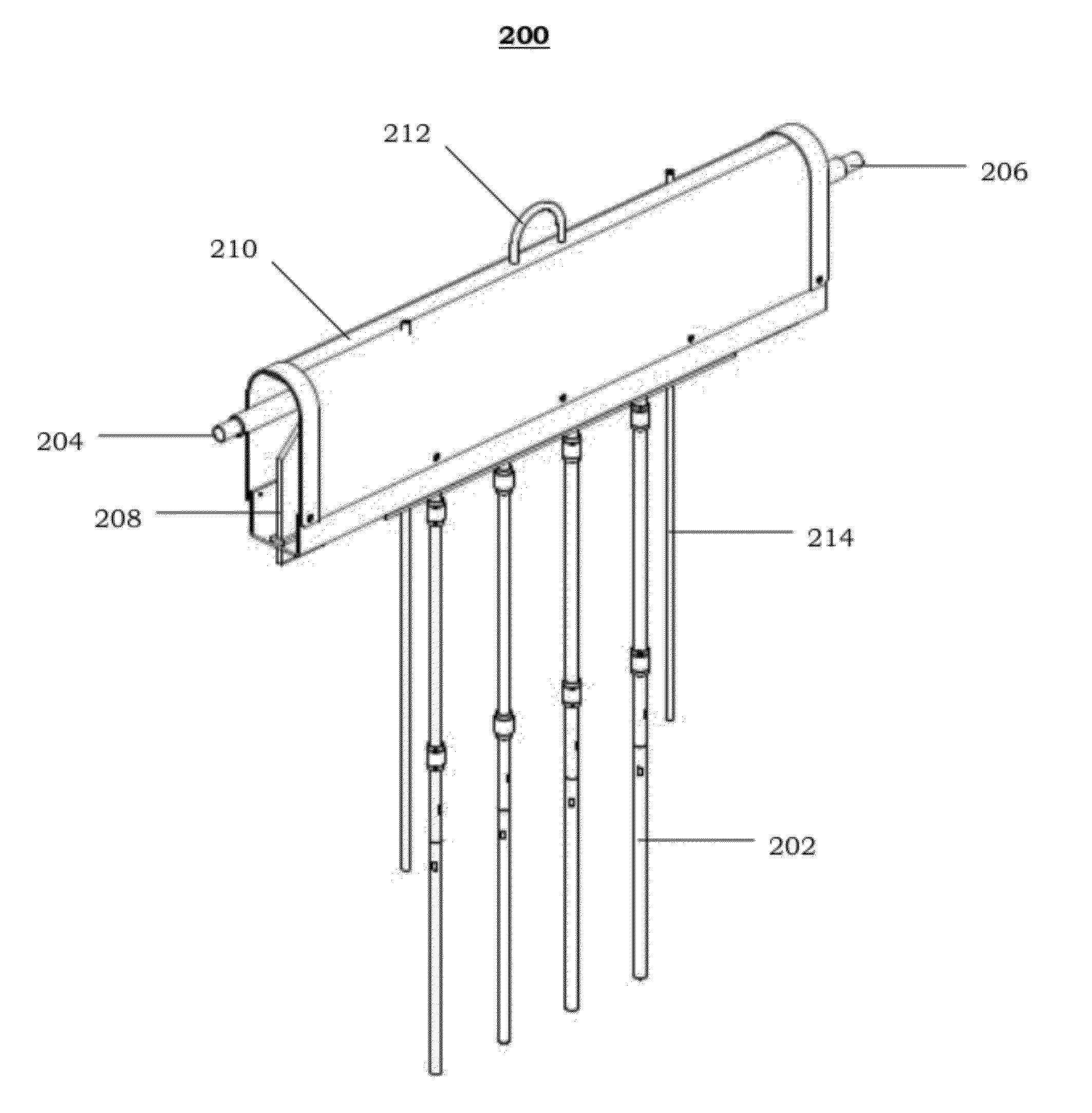
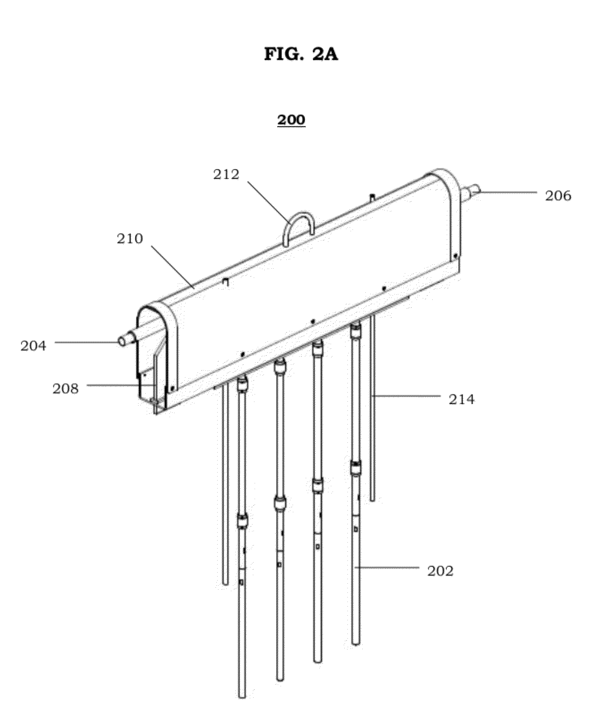
[0009]An anode shroud may be provided for each anode assembly of an electrolytic oxide reduction system to dilute, cool, and/or remove off-gas from the electrolytic oxide reduction system. An anode shroud according to a non-limiting embodiment of the present invention may include a body portion having a tapered upper section that includes an apex. The upper section may slope downwards from the apex. The body portion may have an inner wall that defines an off-gas collection cavity. An underside of the body portion may be unenclosed. A plurality of anode guides may be disposed on

Problems solved by technology

However, a multi-step approach involves a number of engineering complexities, such as issues pertaining to the transfer of molten salt and reductant at high temperatures from one vessel to another.
In particular, this thermodynamic constraint will limit the amount of oxides that can be reduced in a given batch.
However, although a conventional single-step approach may be less complex than a multi-step approach, the metal yield is still relatively low.
Furthermore, reducing a metal oxide to its corresponding metal will result in the production of oxygen gas, which is corrosive and, thus, detrimental to the system if not properly addressed.

Method used


Image

  • Anode shroud for off-gas capture and removal from electrolytic oxide reduction system
  • Anode shroud for off-gas capture and removal from electrolytic oxide reduction system
  • Anode shroud for off-gas capture and removal from electrolytic oxide reduction system

Examples


Embodiment Construction

[0019]It should be understood that when an element or layer is referred to as being “on,”“connected to,”“coupled to,” or “covering” another element or layer, it may be directly on, connected to, coupled to, or covering the other element or layer or intervening elements or layers may be present. In contrast, when an element is referred to as being “directly on,”“directly connected to,” or “directly coupled to” another element or layer, there are no intervening elements or layers present. Like numbers refer to like elements throughout the specification. As used herein, the term “and / or” includes any and all combinations of one or more of the associated listed items.

[0020]It should be understood that, although the terms first, second, third, etc. may be used herein to describe various elements, components, regions, layers and / or sections, these elements, components, regions, layers, and / or sections should not be limited by these terms. These terms are only used to distinguish one eleme...


PUM

PropertyMeasurementUnit
Fractionaaaaaaaaaa
Fractionaaaaaaaaaa
Fractionaaaaaaaaaa

Abstract

An electrolytic oxide reduction system according to a non-limiting embodiment of the present invention may include a plurality of anode assemblies and an anode shroud for each of the anode assemblies. The anode shroud may be used to dilute, cool, and / or remove off-gas from the electrolytic oxide reduction system. The anode shroud may include a body portion having a tapered upper section that includes an apex. The body portion may have an inner wall that defines an off-gas collection cavity. A chimney structure may extend from the apex of the upper section and be connected to the off-gas collection cavity of the body portion. The chimney structure may include an inner tube within an outer tube. Accordingly, a sweep gas / cooling gas may be supplied down the annular space between the inner and outer tubes, while the off-gas may be removed through an exit path defined by the inner tube.

Description

FEDERALLY SPONSORED RESEARCH OR DEVELOPMENT[0001]The present invention was made with Government support under contract number DE-ACO2-06CH11357, which was awarded by the U.S. Department of Energy.BACKGROUND[0002]1. Field[0003]The present invention relates to an anode shroud for an electrolytic oxide reduction system.[0004]2. Description of Related Art[0005]An electrochemical process may be used to recover metals from an impure feed and / or to extract metals from a metal-oxide. A conventional process typically involves dissolving a metal-oxide in an electrolyte followed by electrolytic decomposition or selective electrotransport to reduce the metal-oxide to its corresponding metal. Conventional electrochemical processes for reducing metal-oxides to their corresponding metallic state may employ a single step or multiple-step approach.[0006]A multiple-step approach is typically used when a metal-oxide has a relatively low solubility in the electrolyte. The multiple-step approach may be ...

Claims


Application Information

Patent Timeline
IPC IPC(8): C25B9/00
CPCC25C7/005C25C3/34C25C7/00
Inventor BAILEY, JAMES L.BARNES, LAUREL A.WIEDMEYER, STANLEY G.WILLIAMSON, MARK A.WILLIT, JAMES L.
Owner GE HITACHI NUCLEAR ENERGY AMERICAS
Why Eureka
Try Eureka