Wireless power feeding system

a power feeding system and wireless technology, applied in the direction of near-field systems using receivers, inductances, exchanging data chargers, etc., can solve the problems of reducing the efficiency of power transmission and difficulty in stably transmitting power with high efficiency, so as to improve the efficiency of power transmission and feed power efficiently, the effect of convenient user-friendly power feeding system

Inactive Publication Date: 2012-06-28
SEMICON ENERGY LAB CO LTD
View PDF1 Cites 46 Cited by
  • Summary
  • Abstract
  • Description
  • Claims
  • Application Information

AI Technical Summary

Benefits of technology

[0023]One embodiment of the present invention can provide a wireless power feeding system using the resonance method, which can increase efficiency of power transmission in accordance with the positional relationship between the power receiving device and the power feeding device during power feeding. Thus, the power feeding device can feed power efficiently to the power receiving device. Therefore, the power feeding system can be more convenient for users.

Problems solved by technology

In a wireless power feeding system using the resonance method, the conditions for the high efficiency of power transmission vary depending on the distance from a resonance coil included in a device receiving power (hereinafter called a power receiving device) to a resonance coil included in a device feeding power (hereinafter called a power feeding device), making it difficult to stably transmit power with high efficiency.
If the positional relationship between the power receiving device and the power feeding device change during power feeding, efficiency of power transmission may decrease.

Method used


Image

  • Wireless power feeding system
  • Wireless power feeding system
  • Wireless power feeding system

Examples


embodiment 1

[0035]This embodiment describes a wireless power feeding system in one embodiment of the present invention, which feeds power wirelessly by using the resonance method.

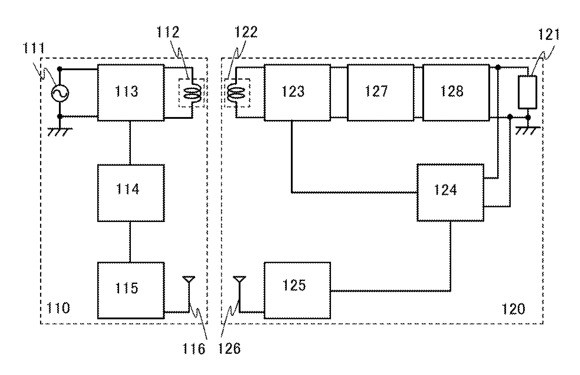
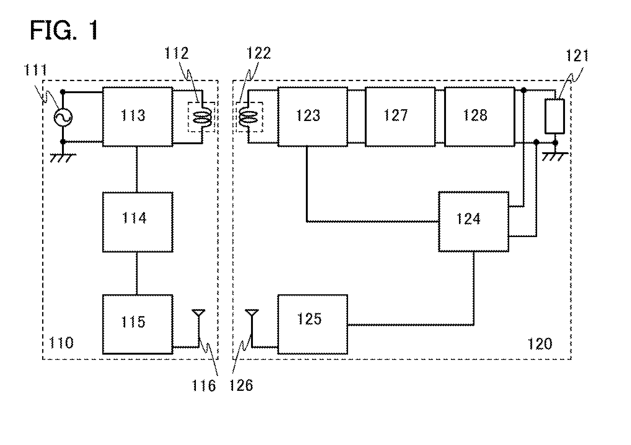
[0036]FIG. 1 shows the configuration of a wireless power feeding system in one embodiment of the present invention. The wireless power feeding system in FIG. 1 uses the resonance method. The wireless power feeding system in FIG. 1 includes a power feeding device 110 and a power receiving device 120. In FIG. 1, a first resonance coil 112 in the power feeding device 110 and a second resonance coil 122 in the power receiving device 120 are in resonance with each other, which enables power transmission by electromagnetic waves.

[0037]The power feeding device 110 includes a high-frequency power source (also referred to as a radio-frequency power source) 111, the first resonance coil 112, a first matching circuit 113, a first control circuit 114, a first transmitter-receiver circuit 115, and a first antenna 116. In the power ...

embodiment 2

[0086]This embodiment describes the applications of the wireless power feeding system in Embodiment 1. Examples of the applications of the wireless power feeding system in one embodiment of the present invention include portable electronic appliances such as digital video cameras, personal digital assistants (e.g., mobile computers, cellular phones, portable game consoles, and electronic book devices), and image reproducing devices including recording media (specifically digital versatile discs (DVDs)); and electric mobile units powered by electricity, such as electric cars. Examples will be described below with reference to drawings.

[0087]FIG. 8A shows the case where the wireless power feeding system is used for a cellular phone or a personal digital assistant. In this case, a power feeding device 701, a cellular phone 702A including a power receiving device 703A, and a cellular phone 702B including a power receiving device 703B are used. The wireless power feeding system in the ab...


PUM


Abstract

A wireless power feeding system includes a power feeding device and a power receiving device. The power feeding device includes a first resonance coil connected to a high-frequency power source through a first matching circuit, and a first control circuit connected to the first matching circuit and a first transmitter-receiver circuit. The power receiving device includes a second resonance coil configured to be in magnetic resonance with the first resonance coil, and a second control circuit connected to a load, a second matching circuit, and a second transmitter-receiver circuit.

Description

BACKGROUND OF THE INVENTION[0001]1. Field of the Invention[0002]The present invention relates to a power feeding device and a wireless power feeding system including the power feeding device.[0003]2. Description of the Related Art[0004]Various electronic appliances have spread and a variety of products is shipped to the market. In recent years, the spread of portable electronic appliances such as cellular phones and digital video cameras is apparent. In addition, electric mobile units powered by electricity, such as electric cars, are going on the market.[0005]A cellular phone, a digital video camera, or an electric mobile unit has a built-in battery serving as a storage battery. Currently, the battery is made, in most cases, in direct contact with a household AC power source, which serves as a power feeding unit, to be charged. In addition, a unit without a battery or a unit which does not use power stored in a battery is currently powered by direct feeding electricity to the unit ...

Claims


Application Information

Patent Timeline
Patent Type & Authority Applications(United States)
IPC IPC(8): H02J17/00H04B5/02
CPCH02J17/00H02J7/025H02J50/12H02J50/80H02J7/00034H02J50/90H02J50/40H01F38/14H02J50/005
Inventor KAMATA, KOICHIROOKANO, SHINYA
Owner SEMICON ENERGY LAB CO LTD
Why Eureka
Try Eureka