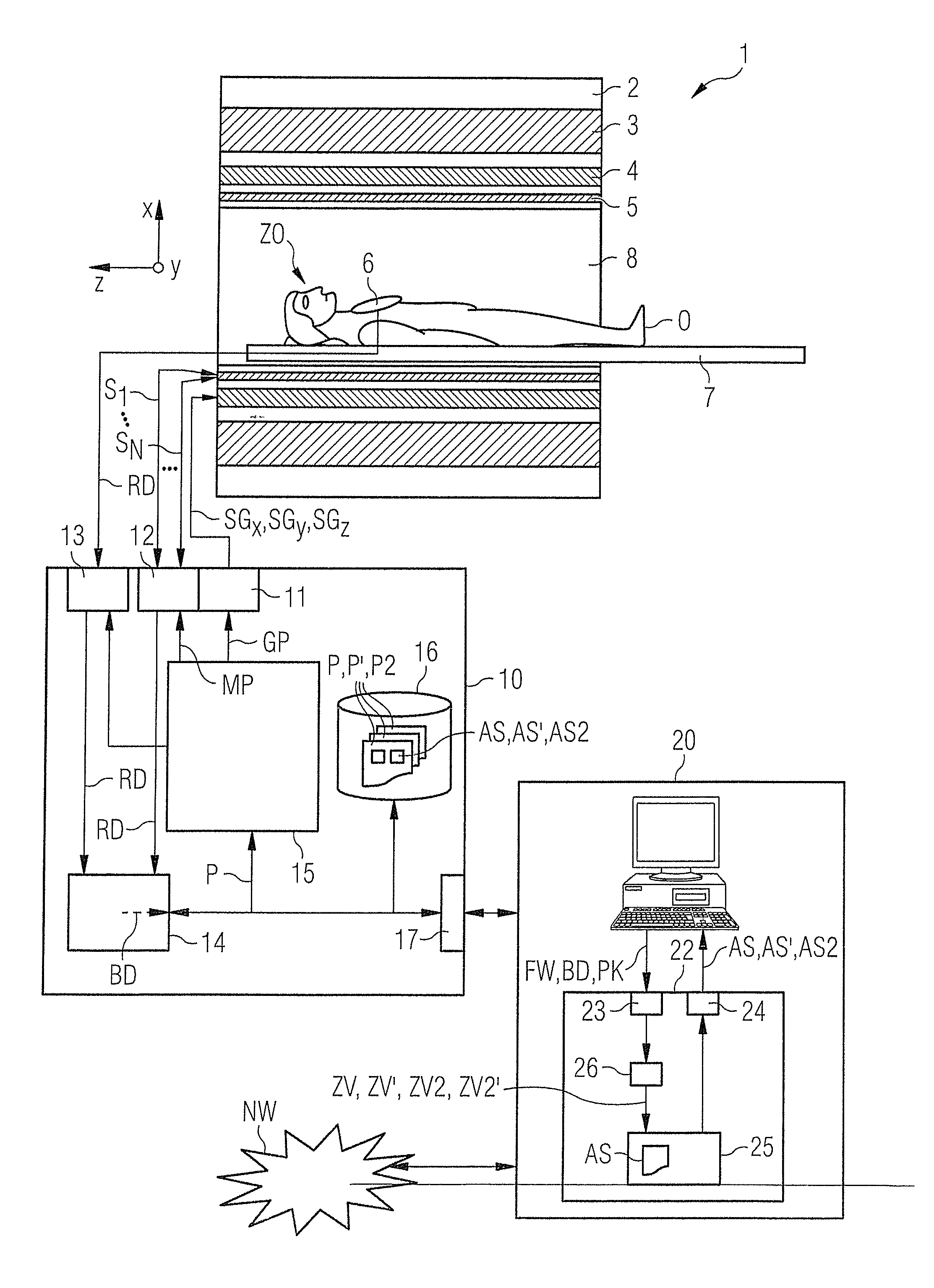
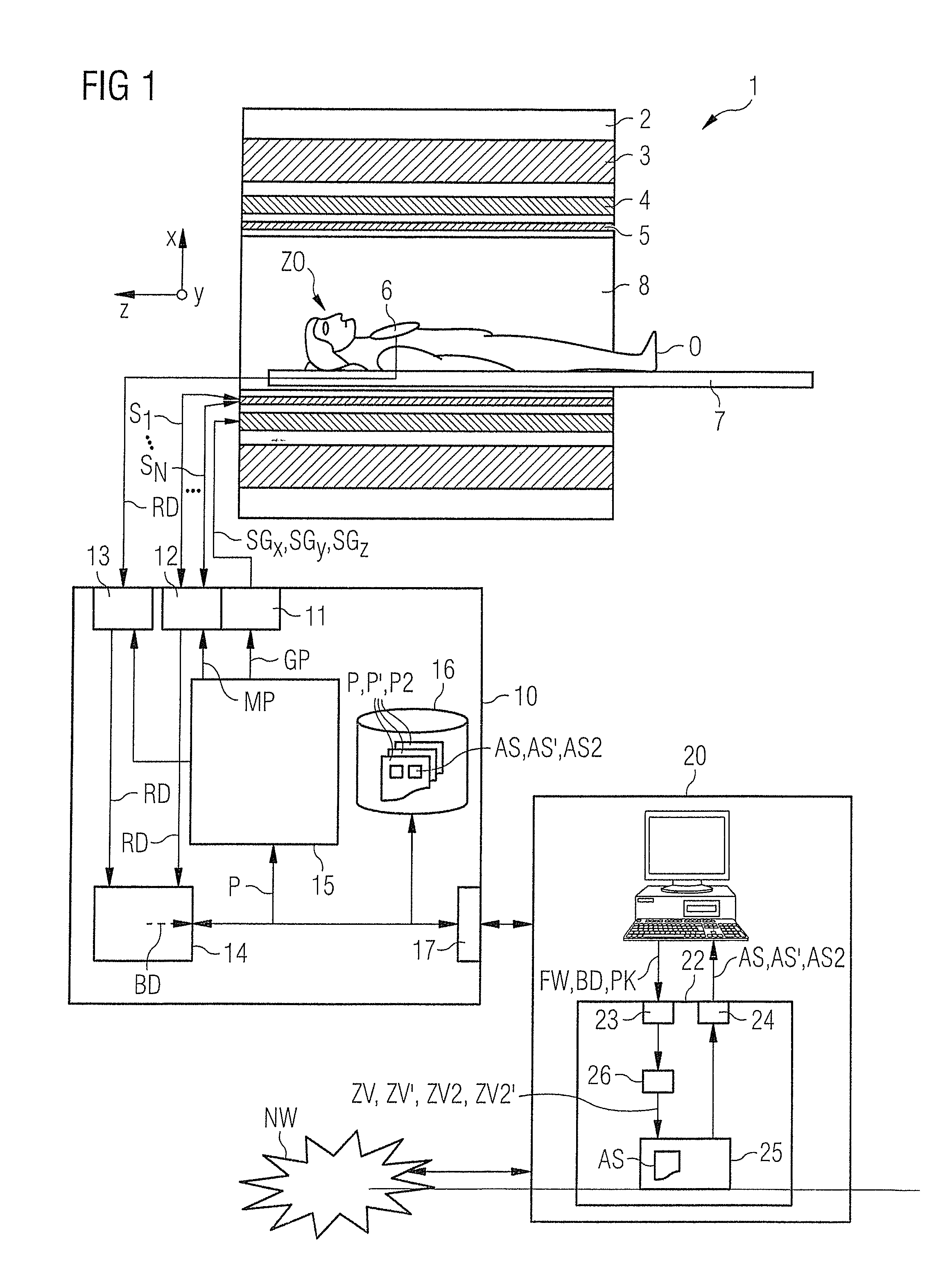
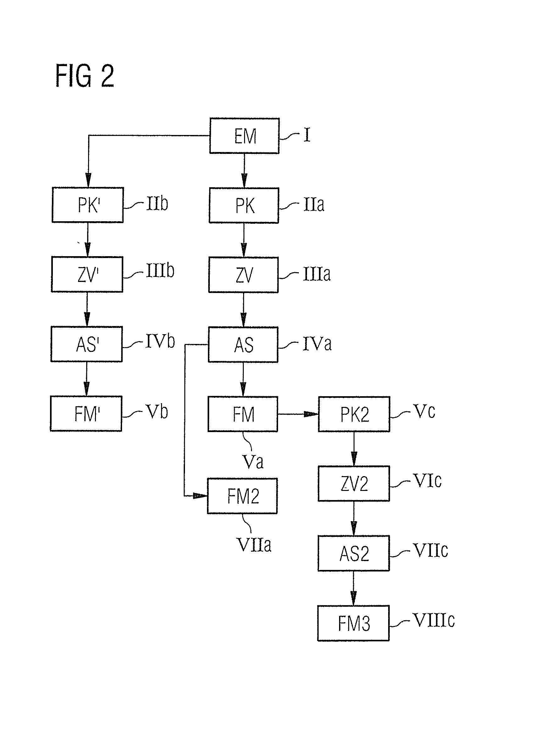
[0013]An object of the present invention is to provide a suitable method and a corresponding control
sequence determination device to determine magnetic resonance activation sequences, which simplify the implementation of such measurements, in particular to assess the treatment progress.
[0016]For example, a destructive therapy can follow the first measurement, the progress of which destructive therapy should be established by one or more follow-up measurements. The same image region is appropriately selected for the follow-up measurement, and the measurement is implemented again with the same
slice thickness and orientation, for example, in order to ensure that the target subject is located at the same position in the image region of the follow-up measurement. However, it is also possible to use different large image regions for the first measurement and the follow-up measurement, for example such that the image region of the follow-up measurement is larger in area than the image region of the first measurement, meaning that the image region of the follow-up measurement is contained in the image region of the first measurement, or vice versa insofar as the target subject is visible in both image regions. The position of the target subject should advantageously be identical in both image regions, for example centrally in the middle, in order to enable a particularly simple comparison.
[0018]By the use of the parameter map based on the image data of the first measurement to determine the local target magnetization, the attitude and dimensions of the target subject can be embedded automatically and (for example) be visualized in the image data of the follow-up measurement since this information also enters into the follow-up measurement via the use of the parameter map. Image data from the follow-up measurement are thus present as a result, which image data contain both the target subject (indirectly via the specific, local target magnetization distribution) with the attitude and the dimensions at the point in time of the first measurement (for example at the beginning of the therapy) and the target subject at the point in time of the process monitoring, and thus allow a direct assessment of the therapy progress after the
visualization of the image data. Automatic representations thus exist that allow a direct assessment of the treatment progress, and in fact without an operator having to mark the target subject (for example the tumor) by hand beforehand by means of an
image processing device.
[0022]The above object is also achieved in accordance with the invention by a non-transitory, computer-readable data storage medium encoded with
programming instructions. When the data storage medium is loaded into a control sequence determination device, the
programming instructions cause the control sequence determination device to implement any or all of the embodiments of the method described above. Similarly, when the data storage medium is loaded into a computerized
control system of a magnetic resonance system, the
programming instructions cause the computerized
control system to operate the magnetic resonance system in any or all embodiments of the above-described method. Such a realization in
software has the
advantage that previous devices that are used to determine control sequences (suitable computers in computer centers of the magnetic resonance system manufacturer, for example) can also be modified via implementation of the program in a suitable manner in order to determine control sequences in the manner according to the invention, which control sequences are connected with a low radio-frequency
exposure.
[0023]The parameter map is particularly preferably based only on image data of the first measurement. No selection—manual or automatic—thus takes place of an image region or a segment of the image region; rather, all image data (and therefore the entire image region) are used. For example, slice images of a follow-up measurement that allow an immediate assessment of the treatment progress can thus be generated without complicated
image processing.
[0034]In principle, the target magnetization distribution can first be determined immediately before the follow-up measurement, using image data from a prior measurement or examination of a patient that has taken place earlier. Alternatively, a control protocol that contains at least one parameter map and / or calculated local target magnetization distribution can also be formed immediately after a first measurement. In addition to this, the control protocol can contain information about the image region or, respectively, section and the
slice thickness and orientation. This control protocol can then already be created at the point in time just after the first measurement and can then be stored. This simplifies the implementation of the follow-up measurements since the stored control protocol simply must only be retrieved, and these data must only be assembled at the point in time of the follow-up measurement or, respectively, the monitoring examination. The control protocol can also be stored on a suitable data medium and be turned over to a patient so that the implementation of follow-up examinations is also possible at other sites and even independent of a given apparatus (within certain limits).


