Temperature-independent chemical and biological sensors

a temperature-dependent, chemical and biological sensor technology, applied in the field of chemical and biological sensors, can solve the problems of complex array fabrication, limited array sensing ability, and difficulty in accurately sensing and discerning a specific type of vapor or vapor mixture being sensed

Active Publication Date: 2012-06-28
GENERAL ELECTRIC CO
View PDF2 Cites 37 Cited by
  • Summary
  • Abstract
  • Description
  • Claims
  • Application Information

AI Technical Summary

Benefits of technology

[0007]In accordance with one embodiment, there is provided a sensor comprising a resonant inductor-capacitor-resistor (LCR) circuit and a sensing material disposed over a sensing region. The sensing region comprises at least a portion of the LCR circuit. Temperature-dependent response coefficients of inductance L, capacitance C, and resistance R properties of the LCR circuit and the sensing material are at least approximately 5 percent different from one another. The difference in the temperature-dependent response coefficients of the properties of the LCR circuit and the sensing material enables the sensor to selectively detect analyte fluids from an analyzed fluid mixture substantially independent of temperature.

Problems solved by technology

However, while using identical sensors simplifies fabrication of the sensor array, such an array may have limited capabilities for sensing only a single response (e.g. resistance, current, capacitance, work function, mass, optical thickness, light intensity, etc).
Disadvantageously, fabricating a sensor array having individual sensors uniquely fabricated to sense a particular response, complicates fabrication of the array.
The greater the number of vapors and vapor mixtures that may be present, the more difficult it may be to accurately sense and discern a specific type of vapor or vapor mixture being sensed.
For instance, high humidity environments often interfere with the ability of traditional sensors to detect selected vapors.
Furthermore, temperature variations reduce the accuracy of chemical and biological sensing when sensors are employed as individual sensors or arranged in an array.

Method used


Image

  • Temperature-independent chemical and biological sensors
  • Temperature-independent chemical and biological sensors
  • Temperature-independent chemical and biological sensors

Examples


example

Accurate Detection of Humidity Levels at Different Temperatures with a Single Sensor

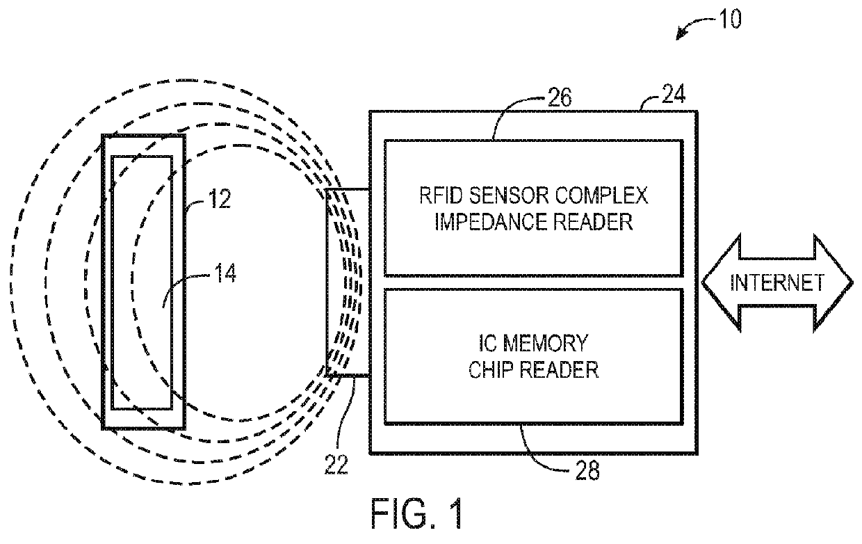
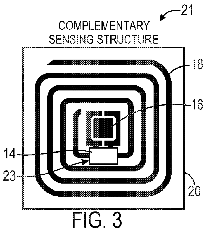
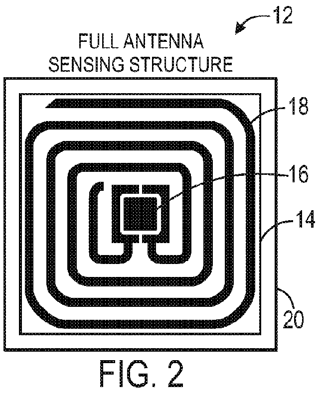
[0075]As illustrated in FIGS. 6-11, test results were obtained to demonstrate the accurate detection of water vapor at several different temperatures, using a single sensor, such as the sensor 12 described above. Such test results may be used to generate the calibration coefficients discussed above with respect to FIG. 5. As illustrated in FIGS. 6, 7, and 9, the sensor was exposed to varying concentrations of water vapor at the following temperatures: 25 degrees Celsius, 30 degrees Celsius, 35 degrees Celsius, and 40 degrees Celsius. Tested concentrations of the water vapor were approximately 0 ppm, 2807 ppm, 4210 ppm, 5614 ppm, 7017 ppm, and 8421 ppm.

[0076]The sensing material used to coat the RFID tag was carefully chosen and provided the ability to accurately detect the concentrations of the water vapor at the four temperatures. In the present experiment, the chosen sensing material was poly(ethe...


PUM

PropertyMeasurementUnit
frequencyaaaaaaaaaa
frequencyaaaaaaaaaa
frequencyaaaaaaaaaa

Abstract

Methods and sensors for selective fluid sensing are provided. A sensor includes a resonant inductor-capacitor-resistor (LCR) circuit and a sensing material disposed over a sensing region. The sensing region comprises at least a portion of the LCR circuit. Temperature-dependent response coefficients of inductance L, capacitance C, and resistance R properties of the LCR circuit and the sensing material are at least approximately 5 percent different from one another. The difference in the temperature-dependent response coefficients of the properties of the LCR circuit and the sensing material enables the sensor to selectively detect analyte fluids from an analyzed fluid mixture substantially independent of temperature.

Description

STATEMENT REGARDING FEDERALLY SPONSORED RESEARCH & DEVELOPMENT[0001]This invention was made with Government support and funded in part by the National Institute of Environmental Health Sciences under Grant No. 1R01ES016569-01A1. The Government has certain rights in the invention.BACKGROUND[0002]The subject matter disclosed herein relates to chemical and biological sensors, and more particularly, to highly selective temperature-independent chemical and biological sensors.[0003]Chemical and biological sensors are often employed in a number of applications where the detection of various vapors may be used to discern useful information. For instance, measuring the presence of vapors by discerning a change in certain environmental variables within or surrounding a sensor may be particularly useful in monitoring changes in biopharmaceutical products, food or beverages, monitoring industrial areas for chemical or physical hazards, as well as in security applications, such as residential ho...

Claims


Application Information

Patent Timeline
Patent Type & Authority Applications(United States)
IPC IPC(8): G01N27/02G01R27/28G01R3/00G01R35/00
CPCG01N27/02Y10T29/49007G01N33/48792G01N27/025G01N27/023G06K19/0717G01N33/02G01N33/22
Inventor POTYRAILO, RADISLAV ALEXANDROVICHSURMAN, CHERYL MARGARET
Owner GENERAL ELECTRIC CO
Why Eureka
Try Eureka