Illumination system and method

a technology of illumination system and illumination plane, applied in the field of illumination system, can solve the problems of preventing the formation of such an analysis apparatus, affecting the detection of eye damage caused by sharp components, and not being able to solve the problem of satisfactory solution

Active Publication Date: 2012-06-28
OCULUS OPTIKGERATE GMBH
View PDF2 Cites 15 Cited by
  • Summary
  • Abstract
  • Description
  • Claims
  • Application Information

AI Technical Summary

Benefits of technology

[0012]It is thus provided to arrange the illumination device laterally beside a nozzle of the actuation device so that a sectional image in the eye can, nevertheless, be generated in an area of the illumination plane lying in the axis of vision, a beam path of the illumination device no longer being obstructed by the actuation device or the nozzle, however. The slit light or illuminating beam path must lie in the illumination plane coinciding with the optical axis so that a maximum deformation of the cornea can be captured. This is made possible because the illumination plane is oriented towards the puff of air. A quality of the illumination and, therefore, of the sectional images can be noticeably improved by the lateral arrangement of the illumination device. It is further possible to also arrange the actuation device completely in the direction of the optical axis, for example, without a curved nozzle feed being necessary. On the whole, the actuation device can thus also be formed in a more compact manner. A further advantage of the laterally inclined arrangement of the illumination device is that the person to be examined is exposed to reduced glare since the light incident into the eye is not projected directly into a central area of a retina of the eye.
[0026]Furthermore, the analysis apparatus can be formed in such a way that the monitoring system, together with the illumination system, can be rotated about an apparatus axis of the actuation device or the optical axis of the eye. It is thus possible to obtain sectional images of the different respective angles of rotation, as a result of which a three-dimensional model of the relevant area of the eye can be derived from the sectional images using the analysis means. In particular, the compact design of the actuation device enabled by the illumination system facilitates the formation of such an analysis apparatus. The monitoring system and the illumination system can thus rotate freely about the apparatus axis because the actuation device can be formed along the optical axis.

Problems solved by technology

In this case, there is the problem that an illumination of the cornea and of an illumination plane in the eye intersecting the axis of vision of the eye is obstructed by a position of the nozzle of the actuation device on the axis of vision.
Although this can be counteracted by forming a transparent region around a nozzle opening and by projecting the slit light through the nozzle opening onto the eye, this is not a satisfactory solution since the slit light cannot be projected onto the eye directly, and therefore without interference.

Method used


Image

  • Illumination system and method
  • Illumination system and method
  • Illumination system and method

Examples


Embodiment Construction

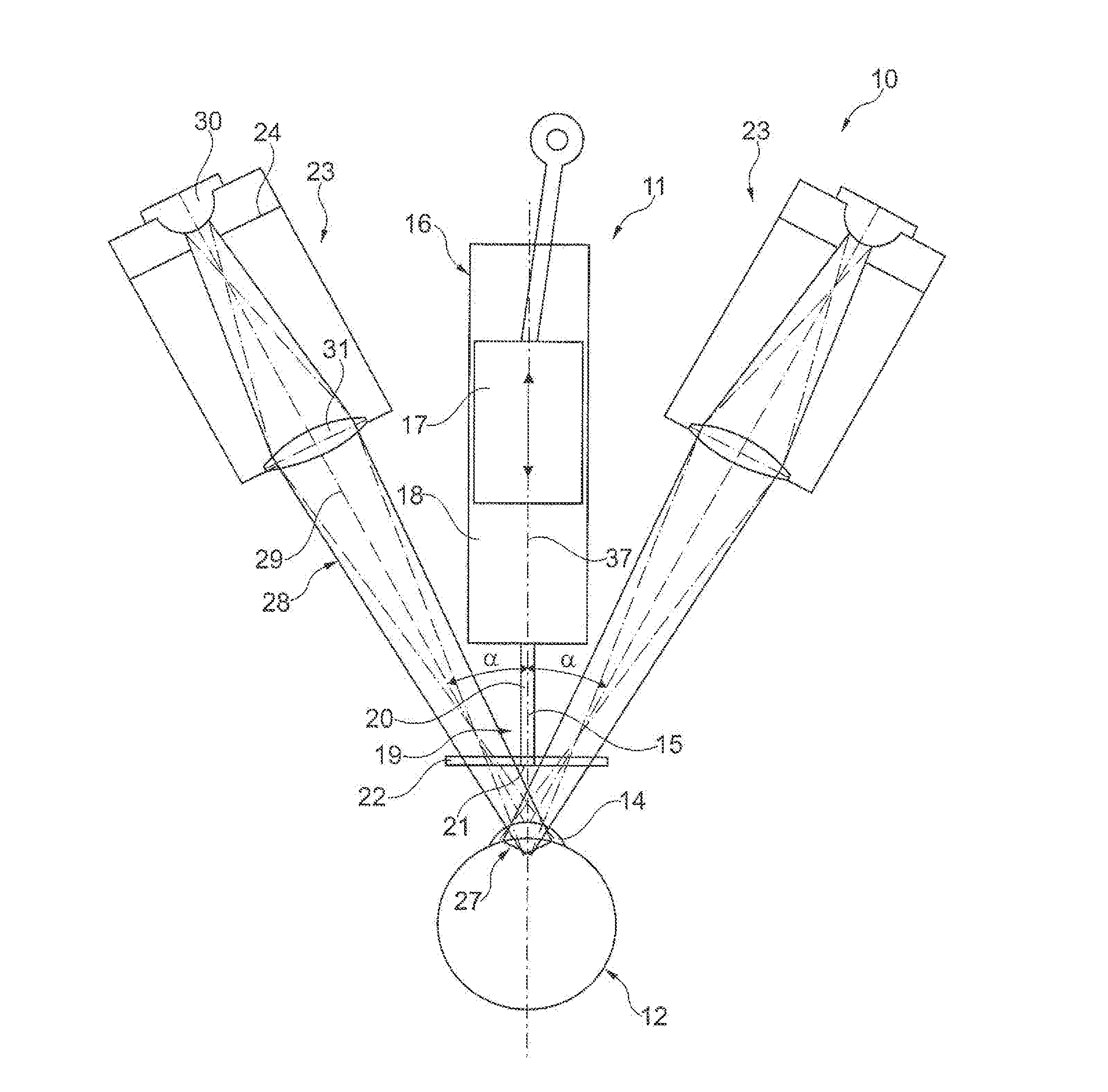
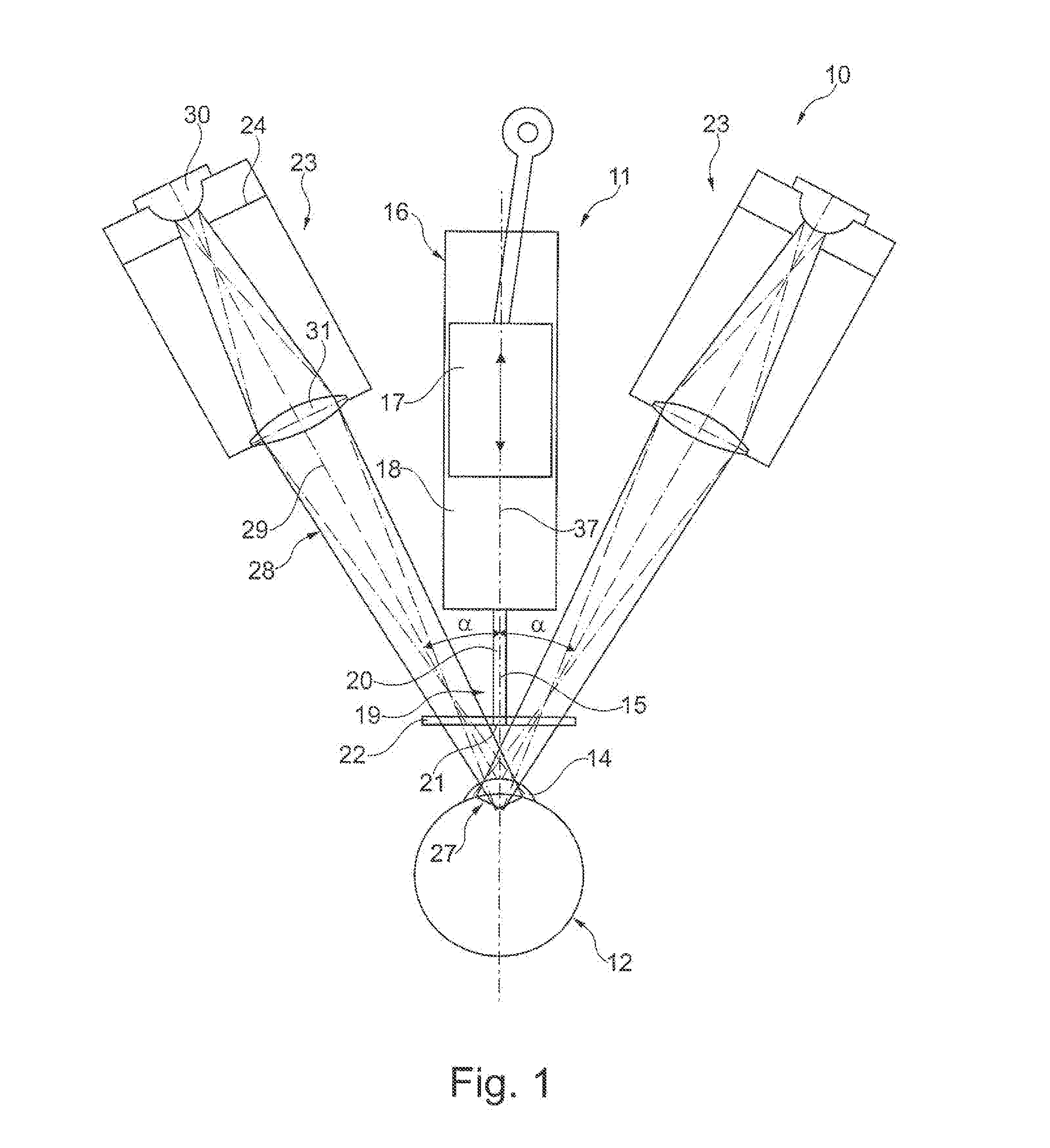
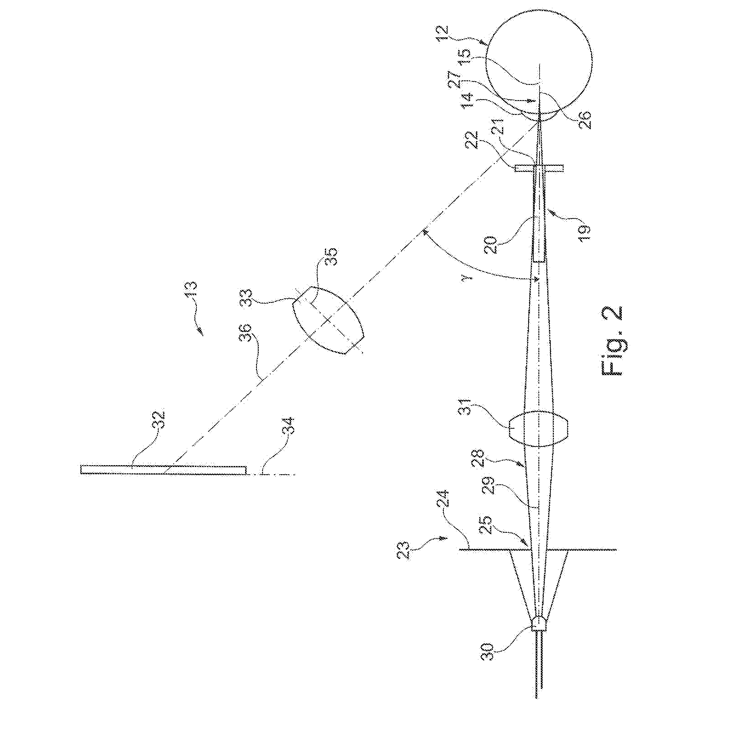
[0035]Viewed together, FIGS. 1 and 2 show an illumination system 10 having an actuation device 11 (shown in part) of an analysis apparatus (not shown in more detail than its components) and an eye 12. In particular in FIG. 2, a monitoring system 13 of the analysis apparatus can also be seen. The analysis apparatus measures an intraocular pressure in the eye 12, wherein a puff of air for deforming a cornea 14 of the eye 12 is applied to the eye 12 using the actuation device 11 in the direction of an optical eye 15 of the eye 12. The actuation device 11 is basically formed of a reciprocating pump 16 with a drive (not shown here in greater detail), and a piston 17, which is arranged so as to be longitudinally movable in a cylinder 18, as well as a nozzle 19. The nozzle 19 comprises a nozzle duct 20, a nozzle opening 21 and a transparent plate 22 in which the nozzle opening 21 is formed. The actuation means 11 is basically arranged along the optical axis 15.

[0036]The illumination system...


PUM


Abstract

The invention relates to an illumination system (10) and an illumination method for an opthalmological analysis apparatus, in particular an analysis apparatus for measuring an intraocular pressure in an eye, wherein the analysis apparatus includes an actuation device (11) with which a puff of air for deforming a cornea (14) can be applied to the eye (12) in the direction of an optical axis (15) of the eye, wherein the illumination system includes at least one illumination device (23) with which the cornea of the eye can be illuminated by a slit light in such a way that a sectional image (27) can be generated in an illumination plane coinciding with the optical axis, wherein the illumination device is formed so that an illuminating beam path (28) of the illumination device oriented towards the eye is arranged at an angle α relative to the optical axis (15).

Description

[0001]This application claims priority from German Patent Application No. 10 2010 049 632.4, filed Oct. 28, 2010, and from German Patent Application No. 10 2011 082 363.8, filed Sep. 8, 2011, the entire disclosures of which are incorporated herein by reference.FIELD OF THE INVENTION[0002]The invention relates to an illumination system for an opthalmological analysis apparatus and to an analysis apparatus having an illumination system, in particular, an analysis apparatus for measuring an intraocular pressure in an eye, wherein the analysis apparatus comprises an actuation device with which a puff of air for deforming a cornea can be applied to the eye in the direction of an optical axis of the eye, wherein the illumination system comprises at least one illumination device with which the cornea of the eye can be illuminated by a slit light in such a way that a sectional image can be generated in an illumination plane coinciding with the optical axis. The invention further relates to ...

Claims


Application Information

Patent Timeline
Patent Type & Authority Applications(United States)
IPC IPC(8): A61B3/10
CPCA61B3/165
Inventor KOEST, GERT
Owner OCULUS OPTIKGERATE GMBH
Why Eureka
Try Eureka