
Autostereoscopic display

a display device and display technology, applied in the direction of paper/cardboard containers, instruments, transportation and packaging, etc., can solve the problems of difficult to meet the needs of precise attention, difficult to install parallax barriers, and difficult to achieve the effect of reducing the cost of installation

Inactive Publication Date: 2012-06-28
IDYLLIC SPECTRUM
View PDF8 Cites 14 Cited by
  • Summary
  • Abstract
  • Description
  • Claims
  • Application Information

AI Technical Summary

Benefits of technology

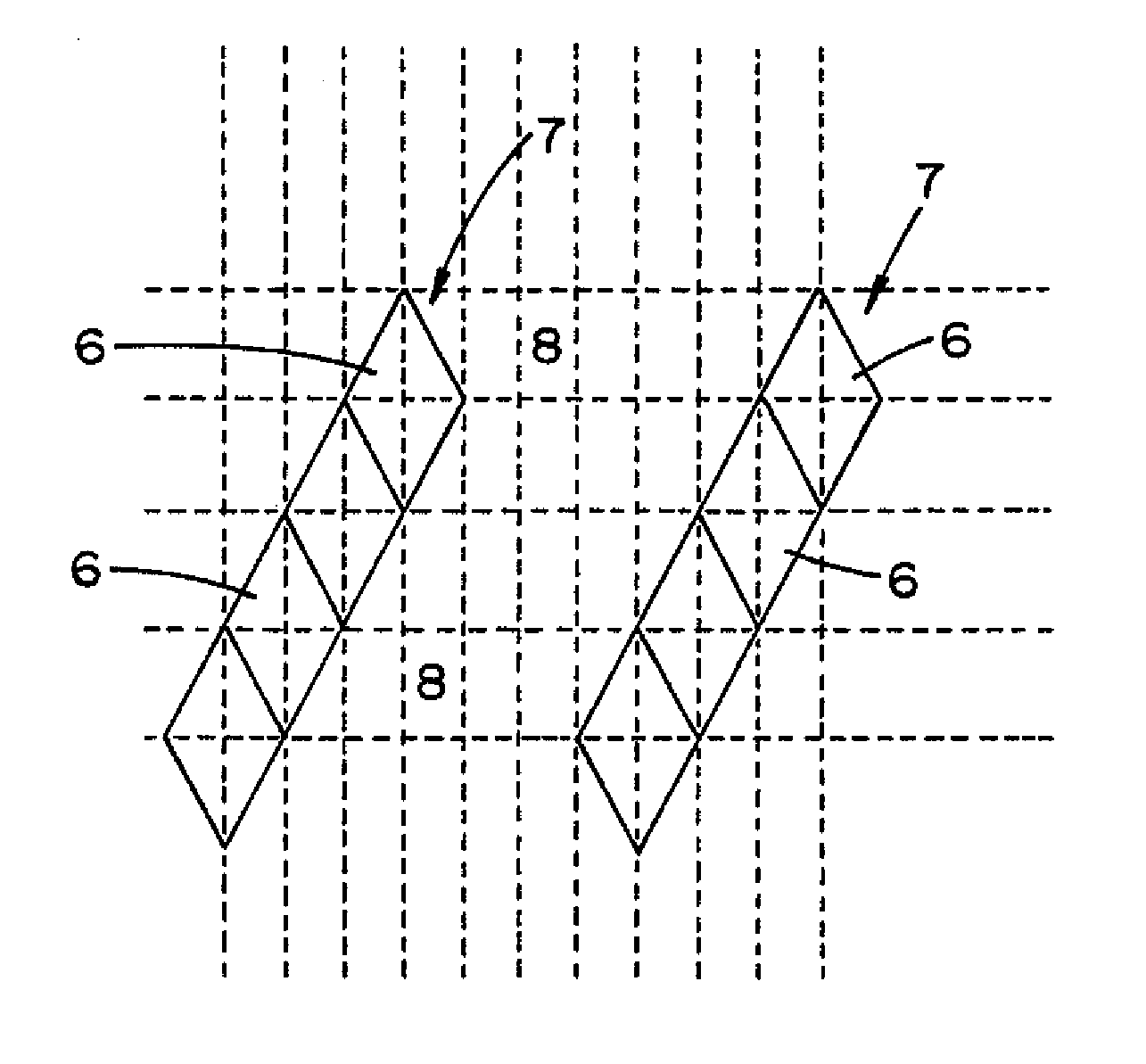
[0016]Due to the particular design of the skewed barrier elements, only one precise and distortion-free installation in horizontal direction is necessary, which considerably simplifies the positioning of the parallax barrier.
[0018]Under the inventive method, the anchoring boxes and the raster created by these forms, have two functions. For one, the form of each anchoring box indicates an enveloping limitation of each structural element. On the other hand, each anchoring box can be addressed via its centre. The raster is formed by the anchoring boxes and covers the entire barrier surface and can be scaled and distorted at random in a functional and simple manner, whereby the position and form of the structural elements are defined and determined in a suitable manner.

Problems solved by technology

A considerable problem with the current forms of parallax-barriers is on for once the not insignificant loss of intensity of the display.
The thus produced parallax barriers consist of vertical arrangements of strips or transverse-running, stair-like arrangements from transparent and / or opaque sections, in which case—due to the angled and star-like form—overlays may appear, particularly Moiré-designs, but other interferences or diffractions may also occur, which often drastically impair the image quality.
Another disadvantage of the currently used barrier systems is that for the angular arrangement of transparent structures, in horizontal as well as in vertical direction, attention must be paid to very precise and non-rotating positioning of structures.
This entails a relatively costly installation of the parallax-barrier, which cannot always be solved in a satisfactory manner.

Method used


Image

  • Autostereoscopic display
  • Autostereoscopic display
  • Autostereoscopic display

Examples


Embodiment Construction

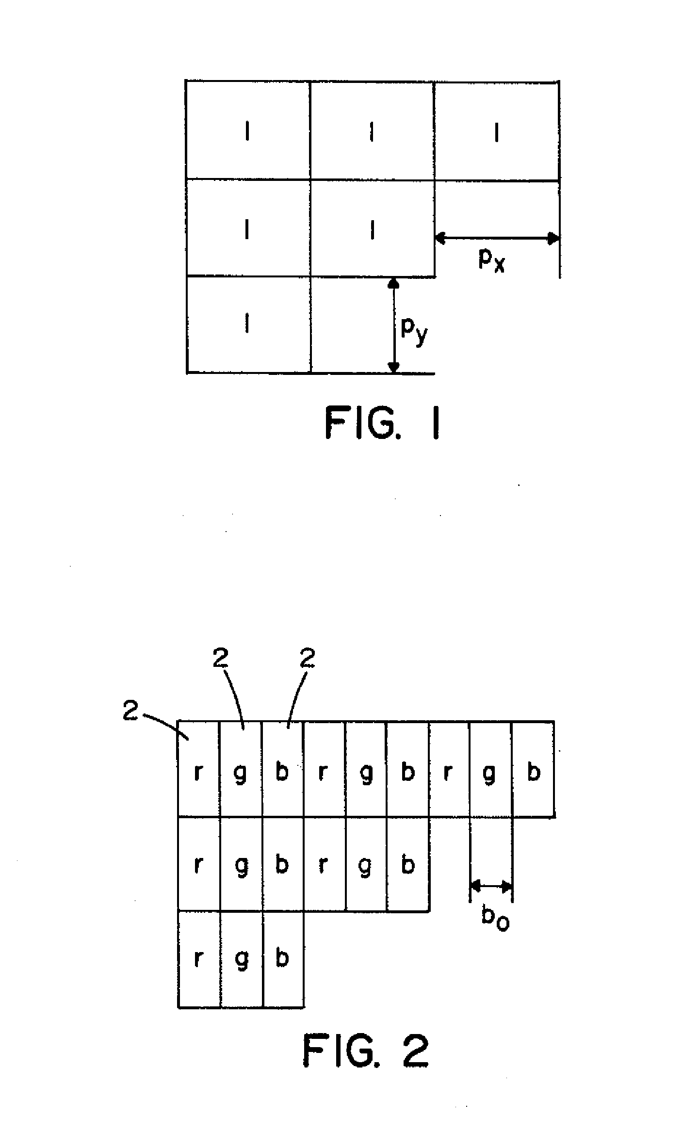
[0045]FIG. 1 shows and explains a group of schematic pixels 1 with a horizontal pixel width px and a vertical pixel height of py. In a colour display the colour value of each pixel is known to be produced by mixed colour additives. As shown in FIG. 2, each pixel is divided into 3 subpixel 2, which radiate a colour value red r, green g and or blue b in different grades of brightness. These sub pixels can be individually accessed and, thus, form the elementary raster element of the display surface. The size of these raster elements is determined by the pixel height py and by the subpixel width bo. The subpixel width bo plays a particularly important role. The subpixels can, technically speaking, be produced as elements of a LC-display, a plasma display or even as part of a conventional electron beam display.

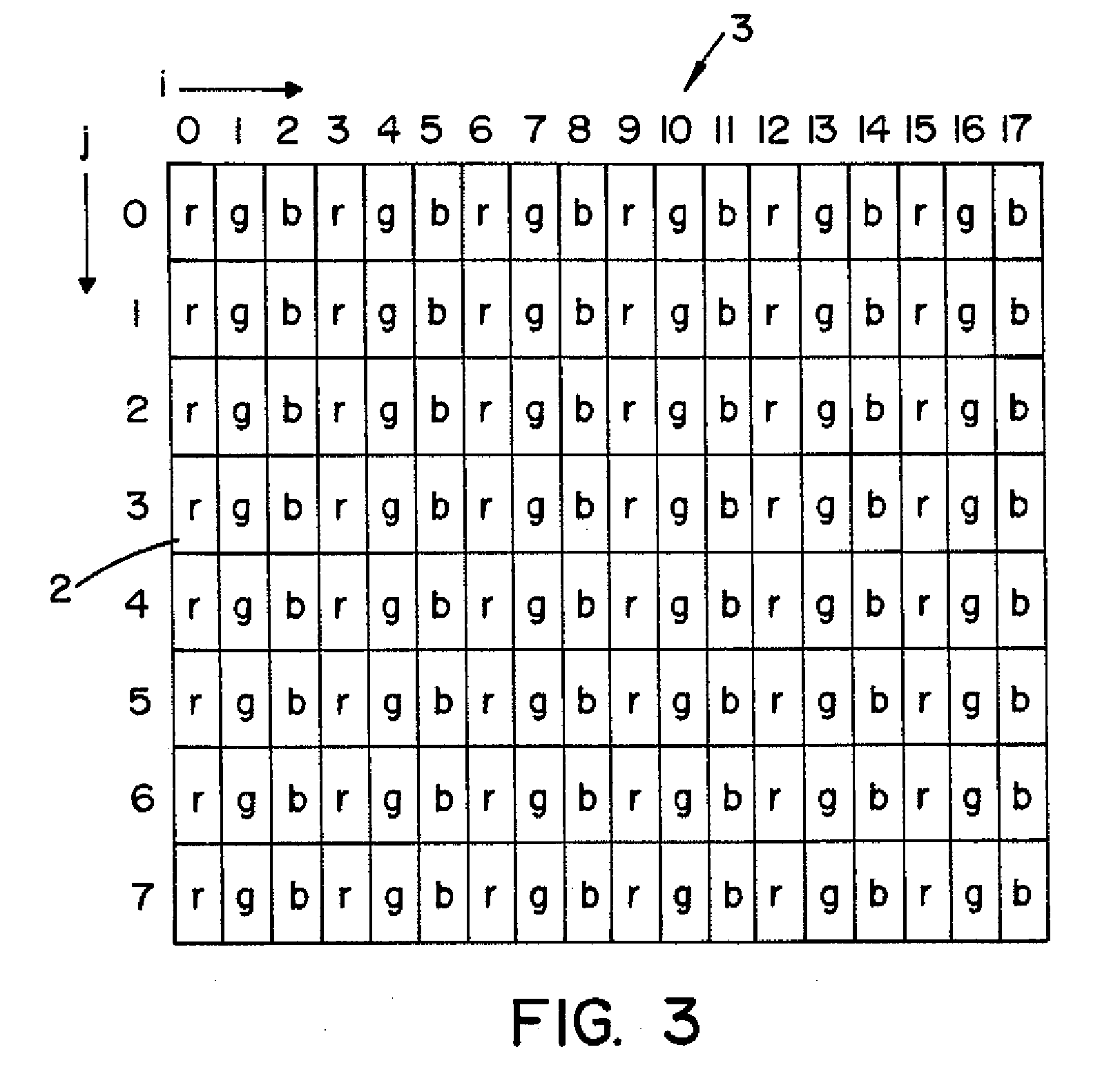
[0046]FIG. 3 shows a segment of a display array 3 with a row of red subpixels r, green subpixels g and blue subpixels b. The position of each individual subpixel of the array is cl...


PUM

PropertyMeasurementUnit
Lengthaaaaaaaaaa
Widthaaaaaaaaaa
Transparencyaaaaaaaaaa

Abstract

A method for creating an autostereoscopic display device including the steps of:providing a display array with a defined pixel arrangement for a number of views (nv), andproviding a parallax barrier that is arranged before and / or behind the display array, wherein the parallax barrier structure is designed with a plurality of structural elements distributed over a barrier surface, whereby a barrier texture is formed by the totality of structural elements which runs skew over the barrier surface,each individual structural element being positioned on the barrier surface based on a virtual raster which is distributed over the barrier surface, the virtual raster is comprised of individual anchoring boxes, wherein a centre of each anchoring box defines the position of one of the totality of the structural elements on the barrier surface, andthe anchoring boxes being scaled with a correction factor that is based on the display device and the number of views (nv),wherein the display array and the parallax barrier are aligned and fixed to each other.

Description

RELATED APPLICATIONS[0001]The present application is a Continuation-in-Part (CIP) of U.S. application Ser. No. 11 / 940,473 filed Nov. 15, 2007 which is fully incorporated herein by reference.FIELD OF THE INVENTION[0002]The invention refers to an autostereoscopic display device and more particularly to the method of making such.BACKGROUND OF THE INVENTION[0003]Autostereoscopic display devices, in particular flat or screen displays, allow for a stereoscopic presentation of a three-dimensional object, which does not require any additional viewing aids like special spectacles and similar items.[0004]For screen and / or flat displays with a defined arrangement of picture points—i.e. pixels and / or sub pixels—array-induced arrangements from a parallax-barrier are used which are arranged before or behind the actual display. In this regard the parallax-barrier is a simple optical system which—together with the defined pixel arrangement, e.g. a LC-display, a plasma-display, an OLED display or ev...

Claims


Application Information

Patent Timeline
IPC IPC(8): G02B27/22B29C65/00G02B30/32
CPCG02B27/2214H04N13/0404Y10T156/10H04N13/0415H04N13/0447H04N13/0409H04N13/305H04N13/31H04N13/317H04N13/351G02B30/32G02B30/27
Inventor GRASNICK, ARMINNARI, AMBROSE PETER
Owner IDYLLIC SPECTRUM
Learn More