LED light bar

Inactive Publication Date: 2012-06-28
SHANGHAI SANSI ELECTRONICS ENG +2
View PDF5 Cites 12 Cited by
  • Summary
  • Abstract
  • Description
  • Claims
  • Application Information

AI Technical Summary

Benefits of technology

[0015]The LED light bar of the present invention has no circuit board for welding LED light sources and adopts metal electricity-conducting plates of highly heat-conducting which reduces the heat resistance and shortens heat-conducting paths to produce higher efficiency and better performance in dissipating heats. Moreover, the electrical electricity-conducting layer is provided in the inner part of the non-electricity-conducting light source mounting

Problems solved by technology

When a LED is used as a light source of a lighting lamp, main problems to be solved in designing are dissipating heats of the light source and waterproofness of the light lamps.
However, such a structure condenses heats in a sealed space and causes unsatisfied heat dissipation results.
The

Method used


Image

  • LED light bar
  • LED light bar
  • LED light bar

Examples


Embodiment Construction

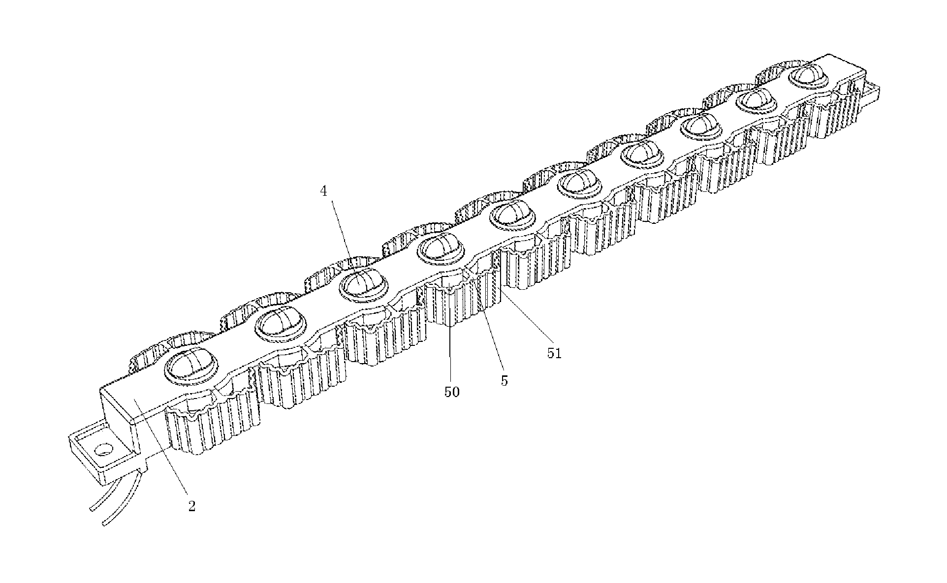
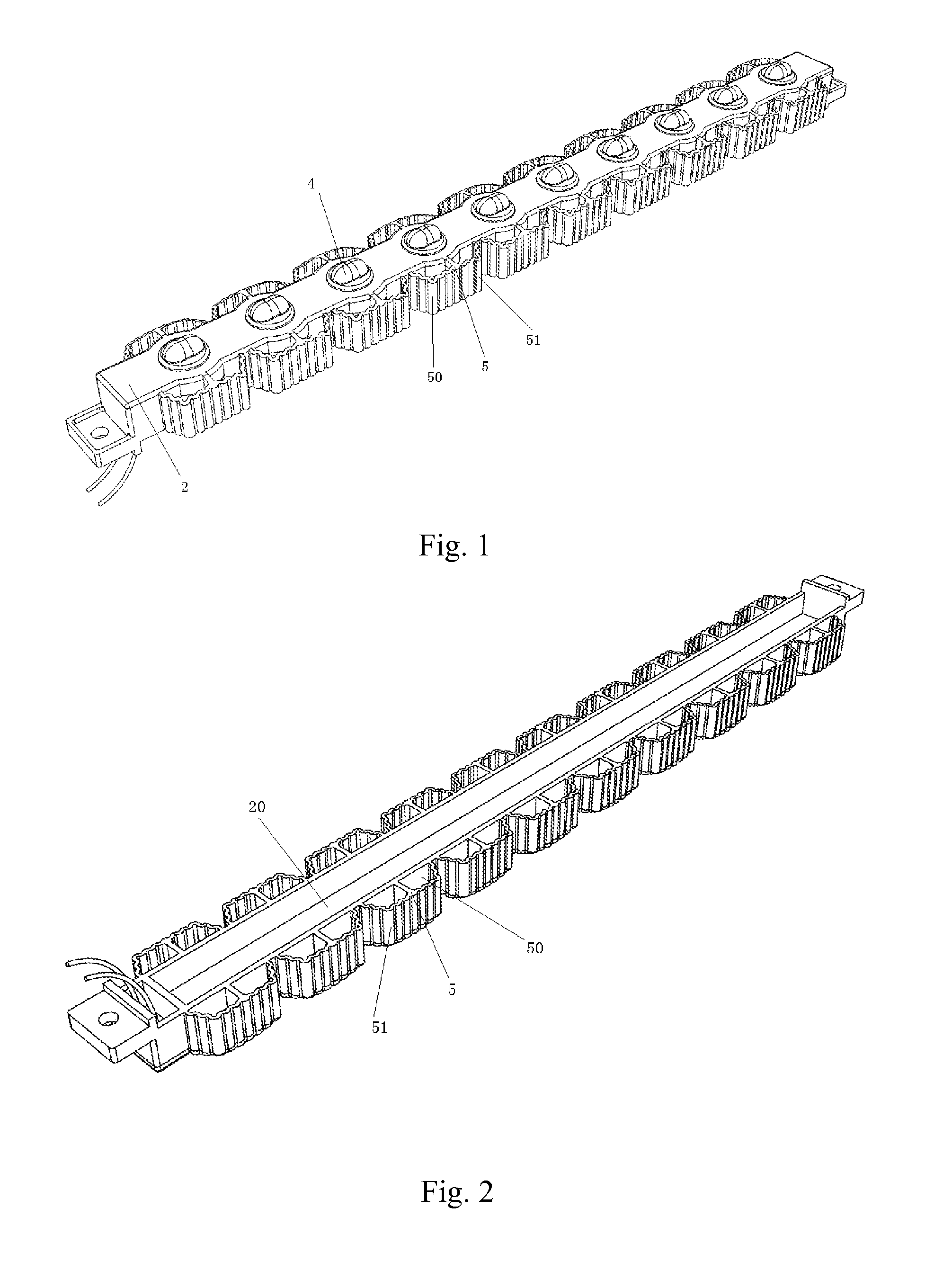
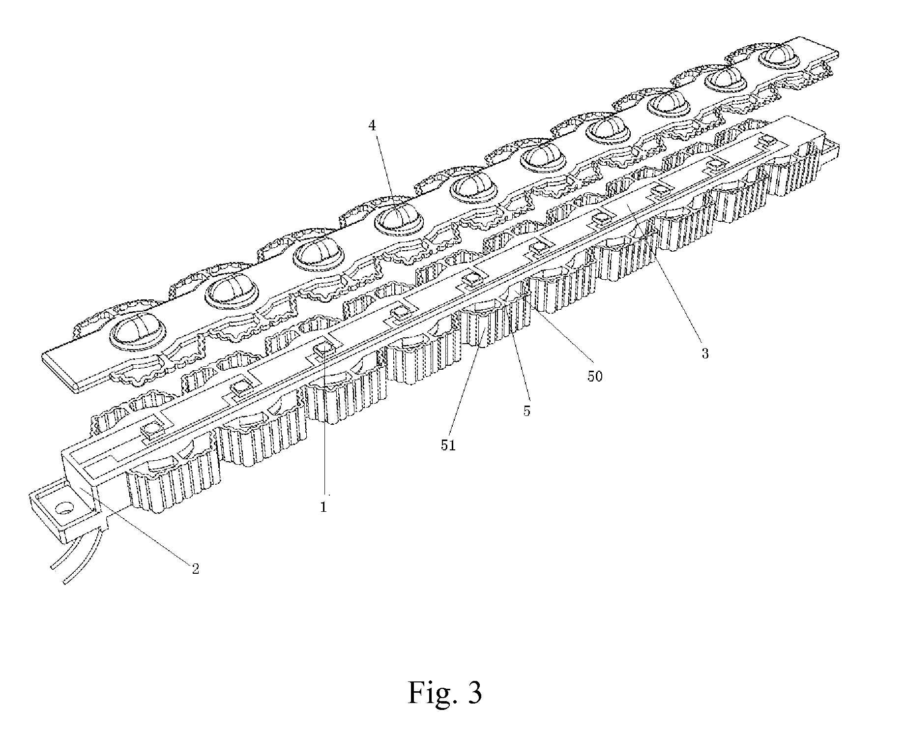
[0020]In FIG. 1, FIG. 2 and FIG. 3, according to a preferred embodiment of the present invention, a LED light bar is illustrated which comprising several LED light sources 1 and a bar light source mounting base 2. The light source mounting base 2 is made of insulating and heat-conducting materials. An electrical layer having several metal electricity-conducting plates is embedded in an inner part of the light source mounting base 2, wherein copper plates 3 of the metal electricity-conducting plates in the preferred embodiment have high heat-conducting coefficients. The light source mounting base 2 and the electrical layer comprising the copper plates 3 are formed into a whole through plastic injection molding. The several copper plates 3 are insulated connected with each other. Pins of positive electrodes and negative electrodes of the LED light sources 1 bridge among the copper plates connected with each other so as to form an electrical electricity-conducting circuit with the copp...


PUM


Abstract

A LED light bar includes several LED light sources and a bar light source mounting base. The light source mounting base is made of an insulating and heat-conducting material. An electrical layer having several metal electricity-conducting plates is embedded in an inner part of the light source mounting base. The LED light sources are welded on the metal electricity-conducting plates to form an electrical electricity-conducting circuit. lighting sides of the LED light sources are exposed on a surface of the light source mounting base. The light source mounting base and the metal electricity-conducting plates are formed into a whole. Each LED light source is covered by lenses.

Description

BACKGROUND OF THE PRESENT INVENTION[0001]1. Field of Invention[0002]The present invention relates to a field of LED lighting, and more particularly to a light bar of a LED lighting lamp having a high heat dissipating efficiency and a high protecting level.[0003]2. Description of Related Arts[0004]When a LED is used as a light source of a lighting lamp, main problems to be solved in designing are dissipating heats of the light source and waterproofness of the light lamps. For example, a conventional road lamp commonly has a front mask and a back cover to satisfy a requirement of dampproofness and waterproofness. However, such a structure condenses heats in a sealed space and causes unsatisfied heat dissipation results. The heavy structure also leads to a big weight and a big cost in materials of the whole lamp.[0005]Besides, the conventional light source is installed integrally, which leads to great inconvenience in installing and maintaining, a low productive efficiency, a low level...

Claims


Application Information

Patent Timeline
IPC IPC(8): F21V29/00F21V5/04
CPCF21V31/00F21S4/008F21V5/007H05K3/202F21V29/87F21Y2103/003H05K2201/10106F21V29/507F21V29/74F21Y2101/02F21S4/28F21Y2103/10F21Y2115/10
Inventor CHEN, MINGQIU, YONGHONGGUO, LIANGWU, JIYE
Owner SHANGHAI SANSI ELECTRONICS ENG
Why Eureka
Try Eureka