Automatic protection switching method, device and system

a technology of automatic protection and switching method, applied in the field of communication technologies, can solve the problems of sharp increase in bandwidth requirements, deterioration of service transmission efficiency and service quality, bandwidth change of microwave link, etc., and achieve the effect of reducing service switching volume, reducing packet loss, and improving efficiency and quality of service transmission

Active Publication Date: 2012-06-28
HUAWEI TECH CO LTD
View PDF2 Cites 60 Cited by
  • Summary
  • Abstract
  • Description
  • Claims
  • Application Information

AI Technical Summary

Benefits of technology

[0022]It can be seen from the forgoing technical solution that, according to the embodiments of the present invention, a technology that performs protection switching for a part of services when the bandwidth of the transmission path changes is used, so as to reasonably utilize the bandwidth resources of the first

Problems solved by technology

In recent years, an IP service gradually replaces the E1 services, and occupies most of traffic in the network, and the requirement for bandwidth sharply increases.
Under such circumstances, since traditional PDH and SDH microwaves cannot well support the IP service, the PDH and SDH microwaves are gradually replaced by a packet microwave technology.
This may lead to the bandwidth change of the microwave link, but may ensure a low bit error rate of service transmission.
Howeve

Method used


Image

  • Automatic protection switching method, device and system
  • Automatic protection switching method, device and system
  • Automatic protection switching method, device and system

Examples


embodiment 1

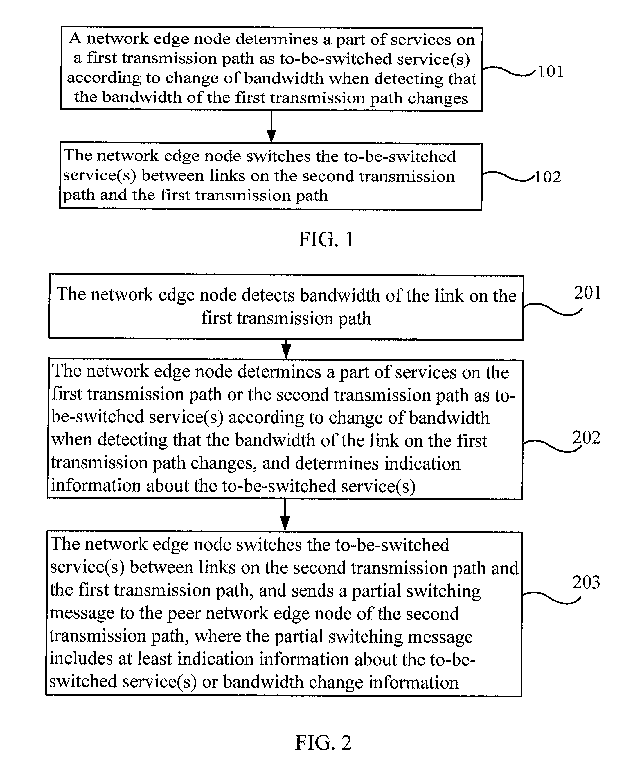
[0048]FIG. 1 is a flow chart of an automatic protection switching method according to Embodiment 1 of the present invention. In a network applying an APS technology, generally at least one protection path and one working path are included. In this embodiment and all the following embodiments, the first transmission path may be a working path, and the second transmission path may be a protection path. Accordingly, when the first transmission path is a protection path, the second transmission path is a working path. Both ends of the second transmission path and the first transmission path are converged to two network edge nodes. These two network edge nodes are configured with a transmitting / receiving selection apparatus, so as to implement protection switching, namely, to determine the path for transmitting the protected service. The method in this embodiment specifically may be performed by either network edge node, and includes the following steps:

[0049]Step 101: The network edge n...

embodiment 2

[0056]FIG. 2 is a flow chart of an automatic protection switching method according to Embodiment 2 of the present invention. This embodiment may be based on embodiment 1 above. Specifically, partial automatic protection switching is triggered according to change of bandwidth. The first transmission path may be a working path, and the second transmission path may be a protection path. The method includes the following steps:

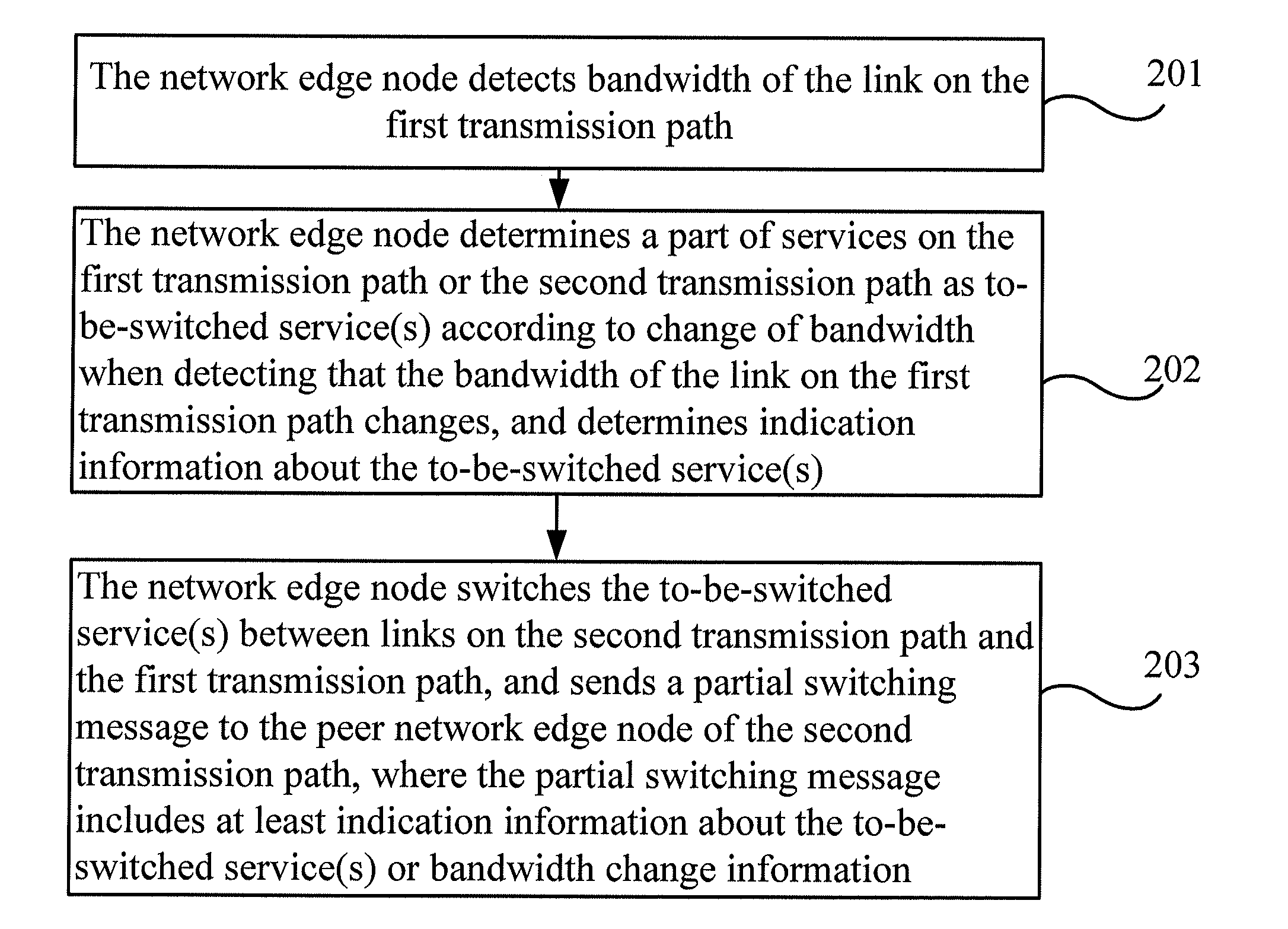
[0057]Step 201: The network edge node monitors bandwidth of the link on the first transmission path.

[0058]Step 202: The network edge node determines a part of services on the first transmission path or the second transmission path as to-be-switched service(s) according to change of the bandwidth when monitoring that the bandwidth of the link on the first transmission path changes; meanwhile, the network edge node may also determine the indication information about the to-be-switched service(s) according to bandwidth change of the first transmission path.

[0059]Step...

embodiment 3

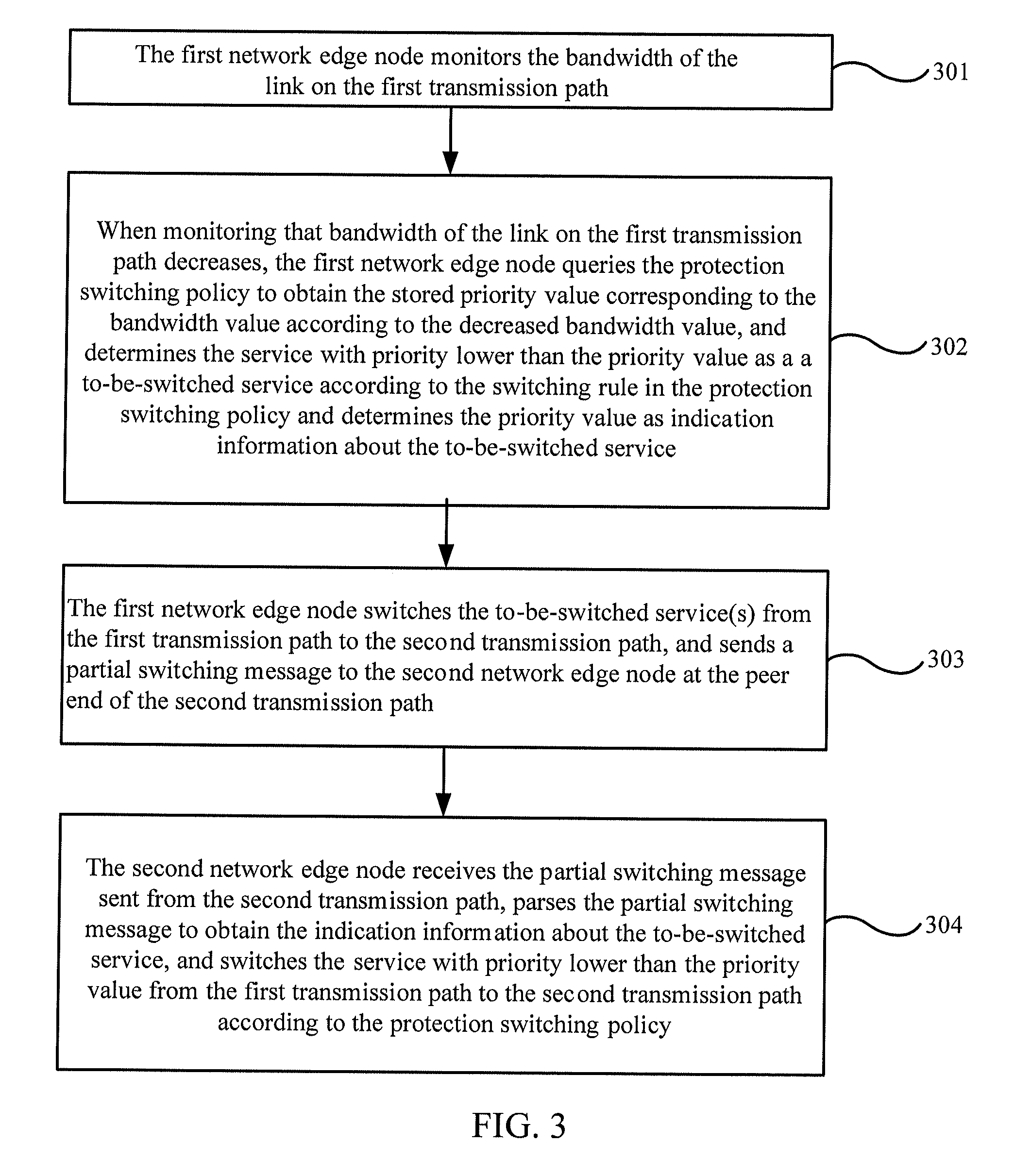
[0068]FIG. 3 is a flow chart of an automatic protection switching method according to Embodiment 3 of the present invention. The APS method in this embodiment may be implemented based on the link arrangement shown in FIG. 4. The APS may include several modes: 1:1, 1:n, and m:n mode. 1:1 refers to one protection path and one working path, where the working path is known as a first transmission path, and the protection path is known as a second transmission path. 1:n refers to one second transmission path and n first transmission paths. m:n refers to m second transmission paths and n first transmission paths, where m and n are natural numbers. The 1:1 mode is taken as an example for illustration. FIG. 4 is a schematic diagram of an automatic protection switching network architecture according to an embodiment of the present invention. As shown in FIG. 4, the links between multiple intermediate nodes form two paths; one is set as the first transmission path 410; and the other is set as...


PUM


Abstract

Embodiments of the present invention provide an automatic protection switching method, device and system. The method includes: determining a part of services as to-be-switched service(s) according to change of bandwidth when monitoring that the bandwidth of the first transmission path changes; and switching the to-be-switched service(s) between links on the second transmission path and the first transmission path. Another method includes: receiving a partial switching message from a peer network edge node through the first transmission path or the second transmission path; and determining the to-be-switched service(s) according to indication information about the to-be-switched service(s) or bandwidth change information in the partial switching message, and switching the to-be-switched service(s) between links on the first transmission path and the second transmission path.

Description

CROSS-REFERENCE TO RELATED APPLICATIONS[0001]This application is a continuation of International Application No. PCT / CN2010 / 072860, filed on May 17, 2010, which claims priority to Chinese Patent Application No. 200910091787.6, filed on Aug. 25, 2009, both of which are hereby incorporated by reference in their entireties.FIELD OF THE INVENTION[0002]The embodiments of the present invention relates to communications technologies, and in particular, to an automatic protection switching method, device, and system.BACKGROUND OF THE INVENTION[0003]A packet transport network (Packet Transport Network, PTN for short) of a communication system uses a link formed by network element nodes to transmit a data packet of a service. To avoid that failure of a part of nodes or links affects service transmission, an automatic protection switching (Automatic Protection Switching, APS) technology is put forward in an existing PTN. That is, a service on a faulty link is switched to a preset standby link ...

Claims


Application Information

Patent Timeline
IPC IPC(8): H04L12/26H04L12/56H04L45/125H04L45/243H04L45/24H04L45/247H04L69/40
CPCH04L41/5025H04L43/0882H04L45/125H04L45/306H04L45/24H04W40/00H04L45/22H04L45/247H04L41/0654
Inventor LONG, HAO
Owner HUAWEI TECH CO LTD
Why Eureka
Try Eureka