
Developing device, image forming apparatus, developer agitating and conveying method

a developer and image forming technology, applied in the field of development devices, image forming apparatuses, and developer agitation and conveying methods, can solve the problems of insufficient frictional charge of compressed developer and the inability of image forming apparatuses to form high quality images, and achieve the effect of reliable charging developer

Active Publication Date: 2012-06-28
SHARP KK
View PDF4 Cites 16 Cited by
  • Summary
  • Abstract
  • Description
  • Claims
  • Application Information

AI Technical Summary

Benefits of technology

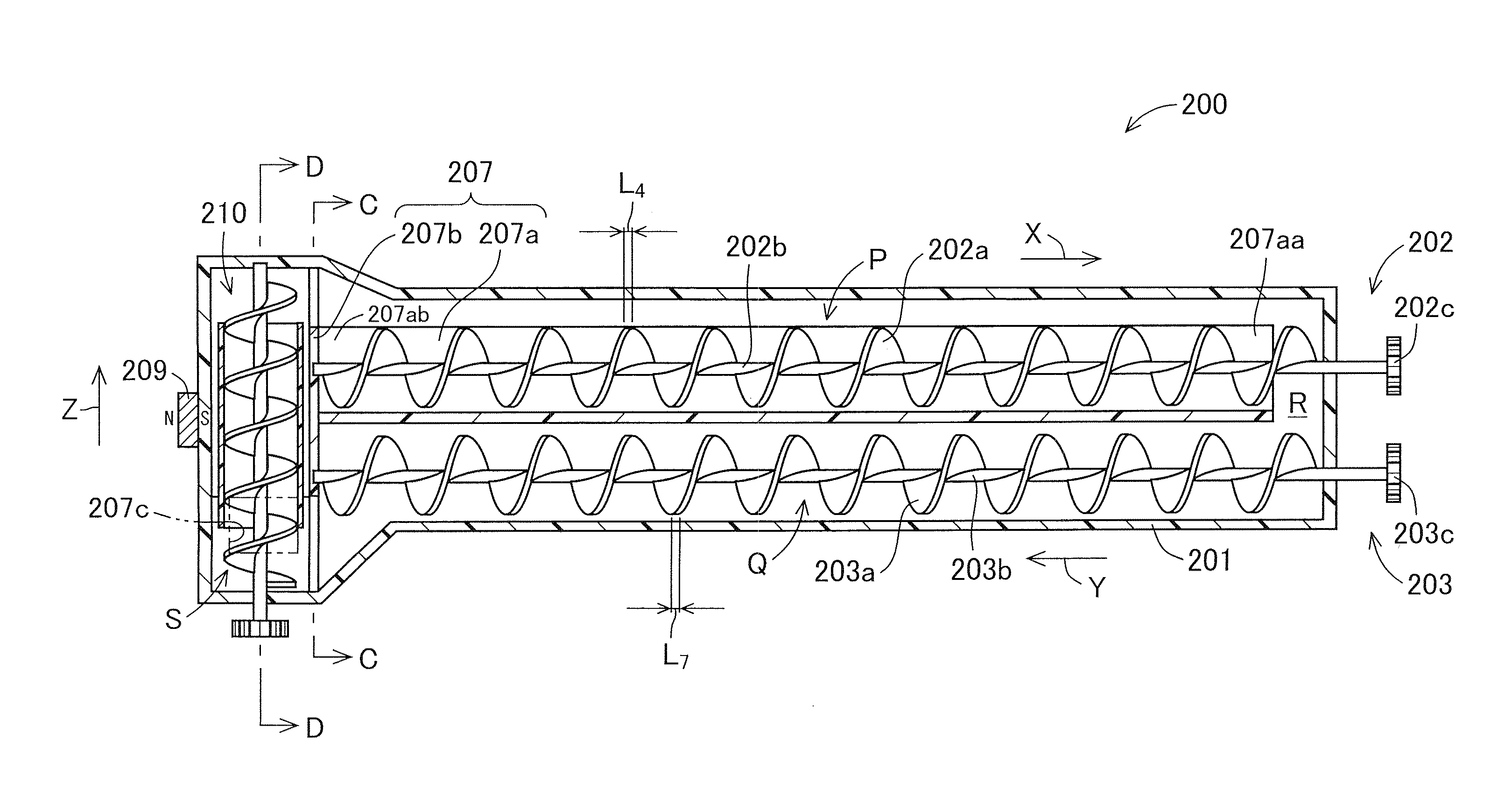
[0024]Further, when being conveyed upward in the vertical direction by the inner spiral blade, the developer in the rotational tube is attracted toward the attracting magnet in the horizontal direction inside the rotational tube in the vicinity of the attracting magnet. The attracted developer is conveyed upward in the vertical direction while pressing the inner wall of the rotational tube. Thus, in a position where magnetic force of the attracting magnet acts on the developer, frictional force between the developer and the inner wall of the rotational tube is increased, which more easily charges the developer. In this way, the developing device according to the technology is capable of sufficiently charging the developer.
[0046]By operating the attracting magnet (electromagnet) intermittently, the horizontal movement of the developer inside the rotational tube due to the attracting magnet (electromagnet) is actively performed, thereby making it possible to reliably charge the developer.

Problems solved by technology

However, in such a developer conveying section, there is a problem that the developer disposed between the spiral blade and a side surface of the fin is compressed and the compressed developer is not sufficiently frictionally charged.
If the developer is not sufficiently charged, the image forming apparatus cannot form a high quality image.

Method used


Image

  • Developing device, image forming apparatus, developer agitating and conveying method
  • Developing device, image forming apparatus, developer agitating and conveying method
  • Developing device, image forming apparatus, developer agitating and conveying method

Examples


Embodiment Construction

[0060]Now referring to the drawings, preferred embodiments are described below.

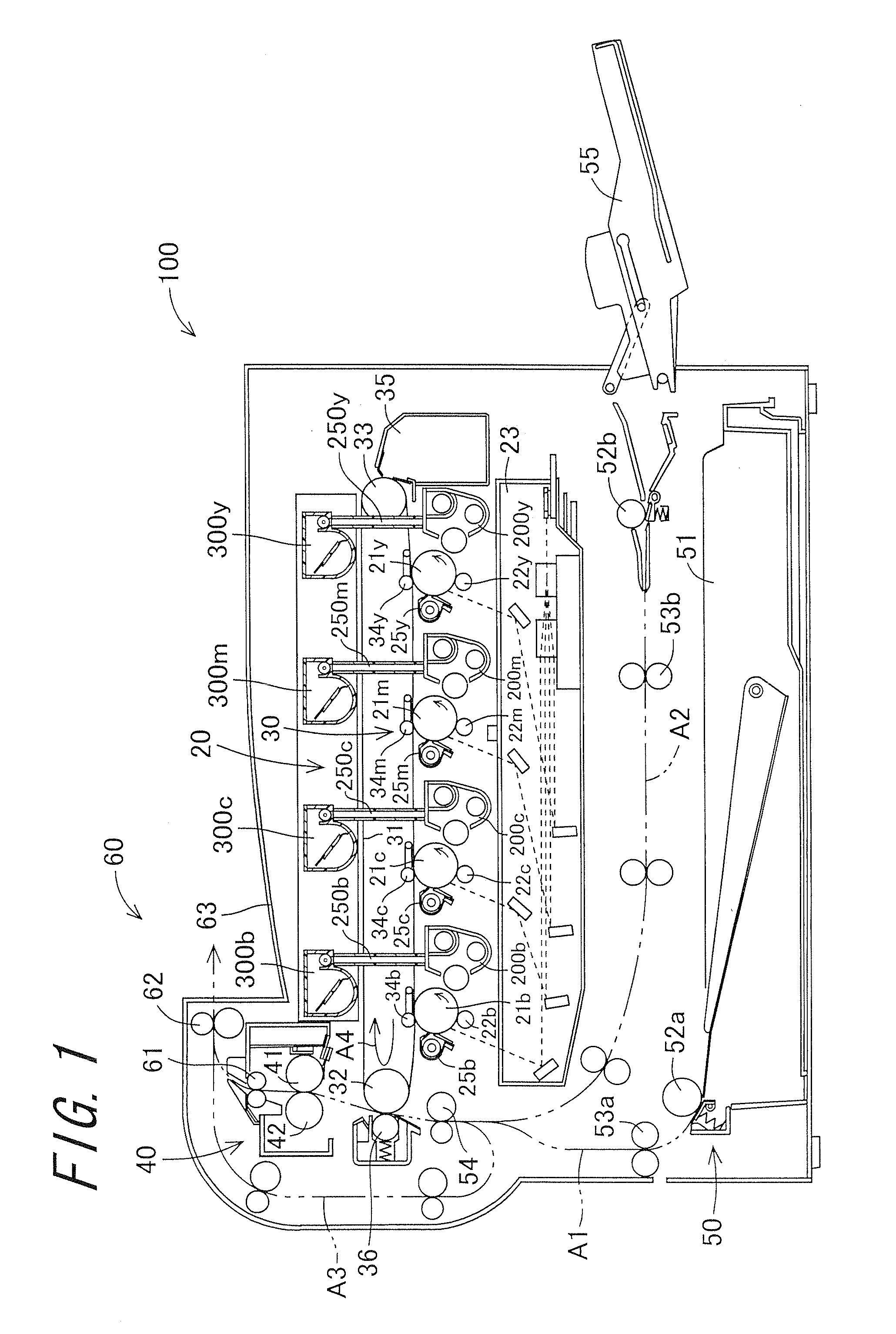
[0061]First, an image forming apparatus 100 having a developing device 200 according to a first embodiment will be described. FIG. 1 is a schematic view showing a configuration of the image forming apparatus 100. The image forming apparatus 100 is a multi-functional peripheral which has a copier function, a printer function, and a facsimile function. A full-color or monochrome image is formed on a recording medium in accordance with the image information transmitted to the image forming apparatus 100.

[0062]The image forming apparatus 100 includes a toner image forming section 20, a transfer section 30, a fixing section 40, a recording medium feeding section 50, a discharging section 60, and a control unit section (not shown). The toner image forming section 20 includes photoreceptor drums 21b, 21c, 21m, and 21y, charging sections 22b, 22c, 22m, and 22y, an exposure unit 23, developing devices 200b, 200c, ...


PUM


Abstract

A developing device includes a developer tank and a developing roller. An internal space of the developer tank is divided into an upper conveying path, a lower conveying path, a communication path, a main pumping conveying path section, and a developer supply path, by a partition wall. A developer pumping conveying section conveys a developer inside the main pumping conveying path section in a conveyance direction Z, and includes an inner spiral blade, a rotational tube, a first outer spiral blade, a second outer spiral blade, a pumping rotation shaft member, and a pumping gear. An attracting magnet is located in a position horizontally spaced from the rotational tube.

Description

CROSS-REFERENCE TO RELATED APPLICATION[0001]This application claims priority to Japanese Patent Application No. 2010-294280, which was filed on Dec. 28, 2010, the contents of which are incorporated herein by reference in its entirety.BACKGROUND OF THE TECHNOLOGY[0002]1. Field of the Technology[0003]The present technology relates to a developing device, an image forming apparatus, and a developer agitating and conveying method.[0004]2. Description of the Related Art[0005]A copier, a printer, a facsimile machine or the like is provided with an image forming apparatus which forms an image employing electrophotography. The electrophotographic image forming apparatus forms an electrostatic latent image on a surface of an image bearing member (photoreceptor) by a charging device and an exposure device, supplies a developer by a developing device to develop the electrostatic latent image, transfers a developer image on the photoreceptor onto a recording medium such as a recording paper by ...

Claims


Application Information

Patent Timeline
IPC IPC(8): G03G15/08
CPCG03G15/0887
Inventor HAYASHI, SHIGEKINAGAI, TAKAFUMI
Owner SHARP KK
Learn More