
Flexible substrate structure and method of fabricating the same

a flexible substrate and substrate technology, applied in the direction of transportation and packaging, coatings, chemistry apparatuses and processes, etc., can solve the problems of high fabrication cost and consequent peeling problems, and achieve the effect of promoting yield rate and quality of flexible substrate structure and reducing fabrication cos

Inactive Publication Date: 2012-06-28
AU OPTRONICS CORP
View PDF3 Cites 46 Cited by
  • Summary
  • Abstract
  • Description
  • Claims
  • Application Information

AI Technical Summary

Benefits of technology

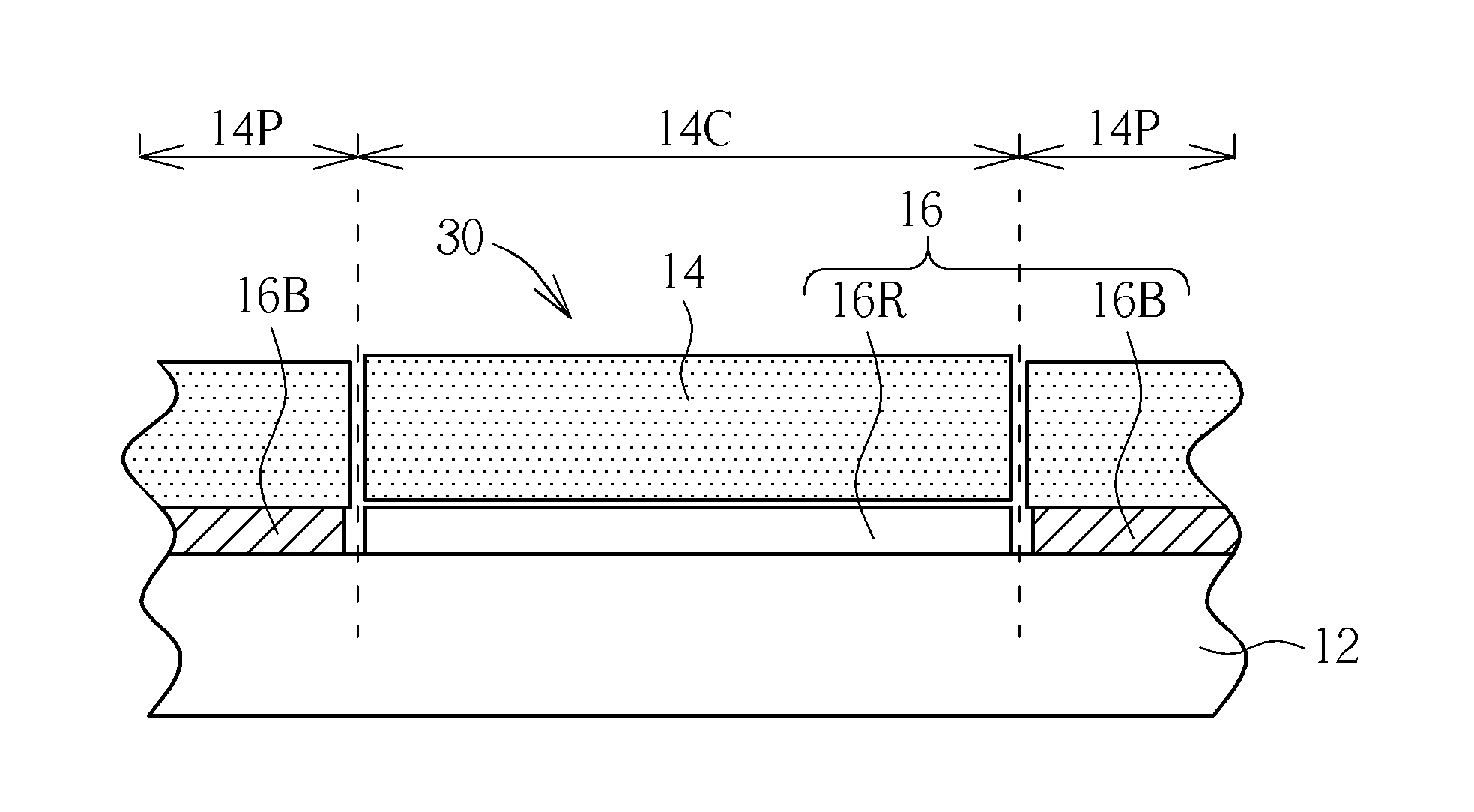
"The present invention provides a flexible substrate structure and a method of making it to reduce fabrication cost, promote yield rate, and quality of the flexible substrate structure. The flexible substrate structure includes a supporting carrier, flexible substrate, and a release layer. The release layer is in contact with both the supporting carrier and the flexible substrate and has adhesion property for bonding them together and supporting them. The method involves forming a bonding region with adhesion property and a release region without adhesion property in the release layer through a local modification process."

Problems solved by technology

A conventional method of fabricating a flexible display device has encountered a bottleneck of fabricating thin film transistors (TFTs) on a flexible substrate, such as a plastic substrate.
However, the conventional method of directly forming the patterned release layer by performing a vacuum evaporation process causes a high fabrication cost.
As a result, the release layer tends to adhere to the shadow mask, which may cause a peeling problem consequently.

Method used


Image

  • Flexible substrate structure and method of fabricating the same
  • Flexible substrate structure and method of fabricating the same
  • Flexible substrate structure and method of fabricating the same

Examples


Embodiment Construction

[0014]To provide a better understanding of the presented invention for one skilled in the art, preferred embodiments will be detailed as follows. The preferred embodiments of the present invention are illustrated in the accompanying drawings with numbered elements to elaborate the contents and effects to be achieved.

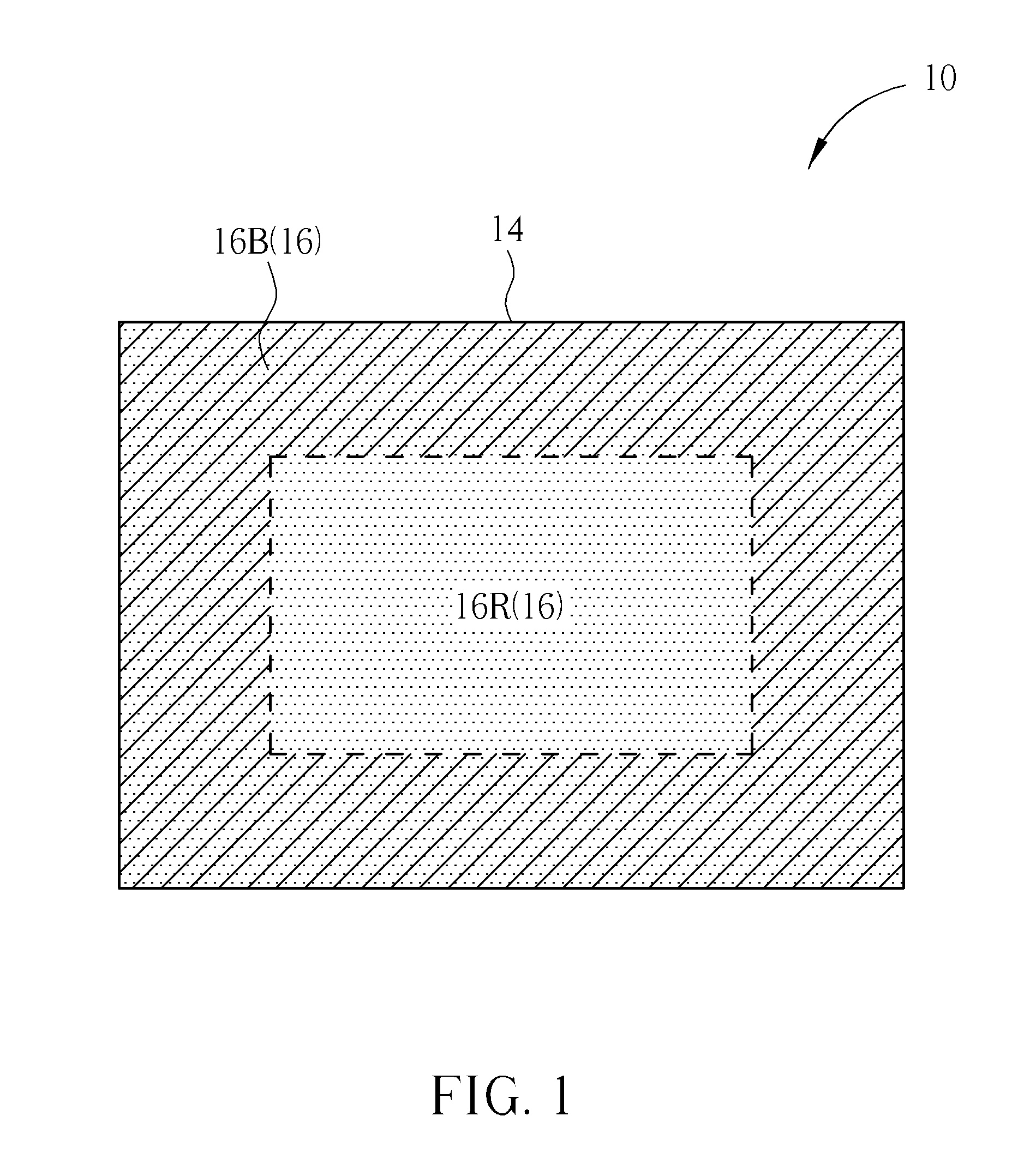
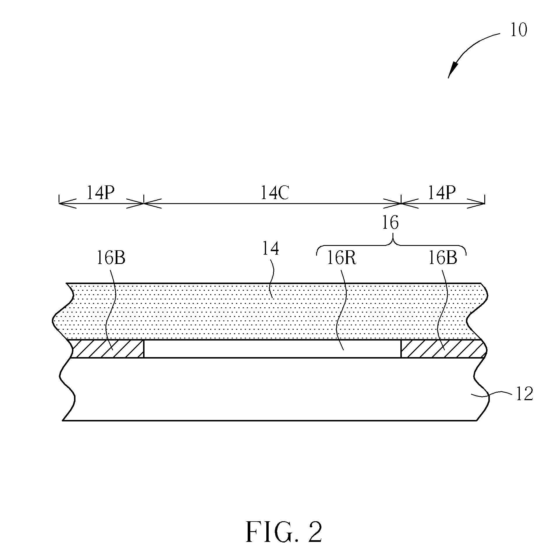
[0015]Please refer to FIG. 1 and FIG. 2, which schematically illustrate a flexible substrate structure according to a preferred embodiment of the present invention. FIG. 1 illustrates a top view of the flexible substrate, and FIG. 2 illustrates a cross-sectional view of the flexible substrate structure. To distinguish features of the flexible substrate structure of the present invention, some components are not shown in FIG. 1. As shown in FIG. 1 and FIG. 2, the flexible substrate structure 10 according to this embodiment includes a supporting carrier 12, a flexible substrate 14, and a release layer 16. Compared to the flexible substrate 14, the supporting carrier 12 is ...


PUM

PropertyMeasurementUnit
temperatureaaaaaaaaaa
exposure timeaaaaaaaaaa

Abstract

A flexible substrate structure includes a supporting carrier, a flexible substrate, and a release layer. The flexible substrate is disposed on the supporting carrier. The release layer is disposed between and in contact with the supporting carrier and the flexible substrate. The release layer includes a bonding region with adhesion property, the bonding region is for bonding the flexible substrate and the supporting carrier together, and a release region without adhesion property, the release region is for supporting the flexible substrate.

Description

BACKGROUND OF THE INVENTION[0001]1. Field of the Invention[0002]The present invention relates to a flexible substrate structure and a method of fabricating the same, and more particularly, to a method of fabricating a flexible substrate structure including forming a bonding region with adhesion property and a release region without adhesion property on a release layer with a local modification process, and a flexible substrate structure thereof.[0003]2. Description of the Prior Art[0004]In modern display technologies, flexible display device is distinguished for its characteristics such as light weight, impact endurance, flexibility, wearability, portability, etc. Thus, the flexible display devices are regarded as a foresighted display technology. A conventional method of fabricating a flexible display device has encountered a bottleneck of fabricating thin film transistors (TFTs) on a flexible substrate, such as a plastic substrate.[0005]In accordance with the conventional method o...

Claims


Application Information

Patent Timeline
Patent Type & Authority Applications(United States)
IPC IPC(8): B32B7/06B32B7/12B32B38/16B05D5/10B32B38/10
CPCB32B7/06B32B7/12B32B2405/00Y10T428/2486C09J5/00Y10T156/1195H01L27/1218
Inventor HWU, KEH-LONGWANG, PIN-FANHU, CHIH-JEN
Owner AU OPTRONICS CORP
Learn More