Saved power measuring circuit

a power measurement and circuit technology, applied in the field of saving power measuring circuits, can solve the problems of difficult to measure the factors of electricity usage, the electric appliance load still works in standby mode, and the difficulty of doing these measurements, so as to save power, save power, and save power. the effect of saving power

Inactive Publication Date: 2012-06-28
PRODIGIT ELECTRONICS
View PDF2 Cites 3 Cited by
  • Summary
  • Abstract
  • Description
  • Claims
  • Application Information

AI Technical Summary

Benefits of technology

[0007]Thus, an objective of the present invention is to provide a saved power measuring circuit, which is able to calculate saved power of the electric appliance load in power saving mode according to the power consumption and the operation time in operation mode.
[0010]In efficient aspect, the present invention uses a simple circuit configuration to measure saved power of the electric appliance load in power saving mode, so that users can understand the accurate power consumption and saved power of the electric appliance load.

Problems solved by technology

But for general residents and workers unfamiliar with electric engineering, they have difficulty in doing these measurements.
Furthermore, it's very hard for them to measure factors of electricity usage, such as power usage (KWHr), power factor, wattage, and etc.
But in fact these electric appliance loads still work in standby mode, and still consume energy.
Although each electric appliance load consumes a few power in standby mode, the total power consumption of electric appliance loads in one house are relatively high.
However, whether the power of electric appliance load is turned off by automatic power saving controller, user's manual operation or the other control signal, users still have no idea about how much power have been saved.
With the requirement of energy saving and carbon dioxide reduction nowadays, although users understand the details of power measurement and power configuration of electric appliance loads in operation mode, they still can not understand the amount of saved power in power off mode and standby mode.

Method used


Image

  • Saved power measuring circuit
  • Saved power measuring circuit
  • Saved power measuring circuit

Examples


Embodiment Construction

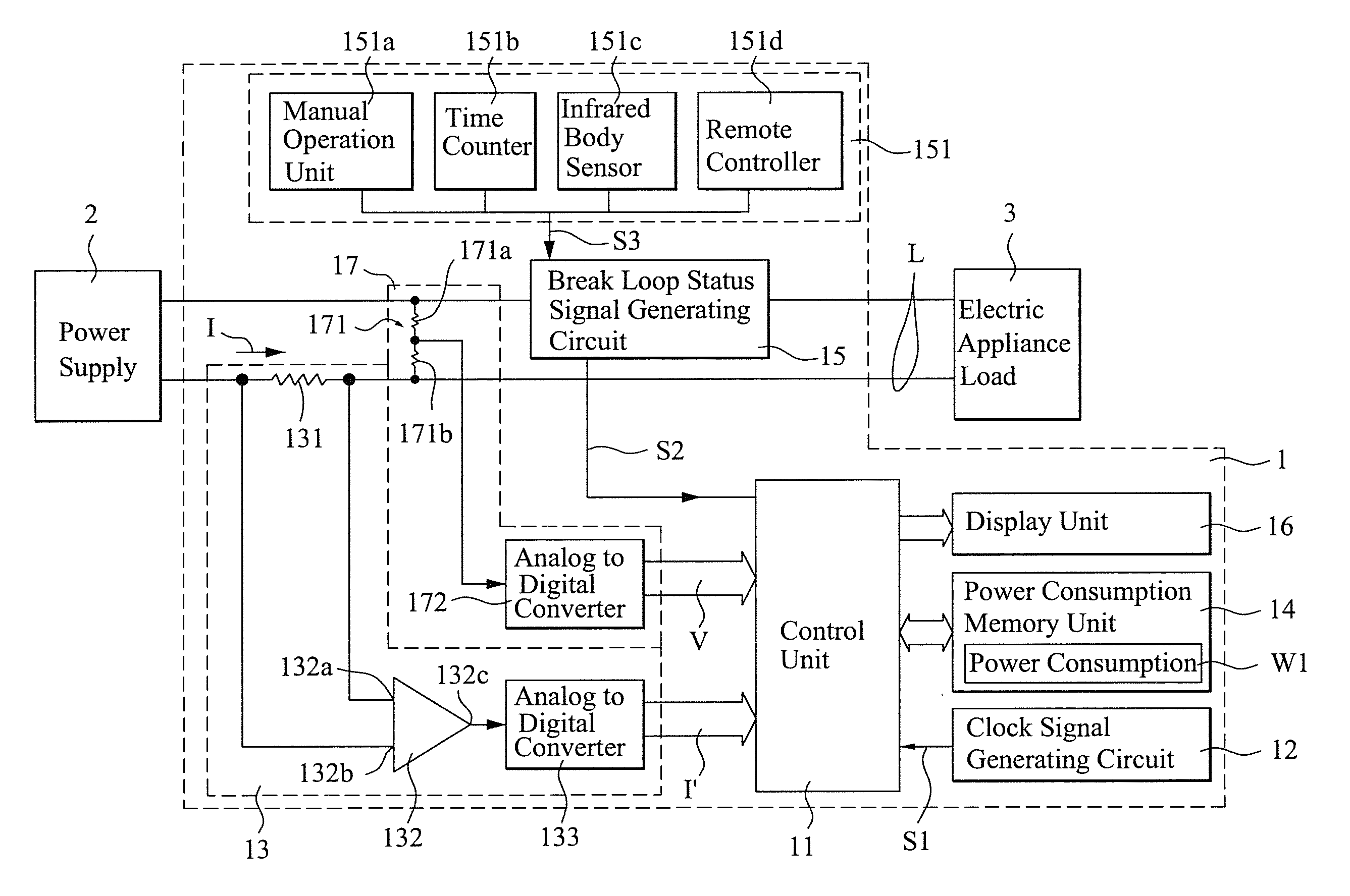
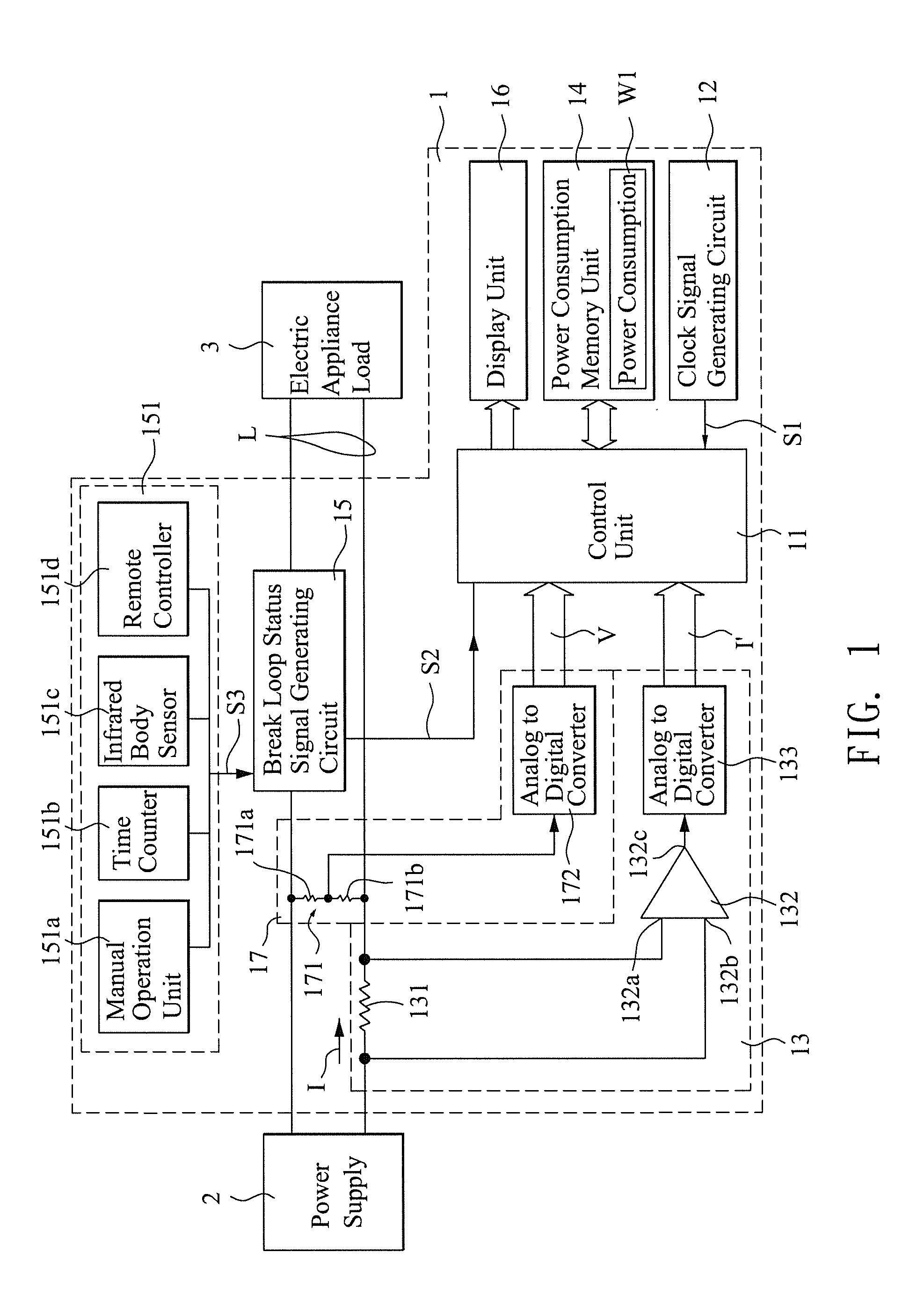
[0015]FIG. 1 shows a circuit diagram of the first embodiment in the present invention. The saved power measuring circuit 1 is connected between a power supply 2 and an electric appliance load 3, the saved power of the electric appliance load 3 switched from operation mode to power saving mode can be measured by the usage of the saved power measuring circuit 1 in the present invention.

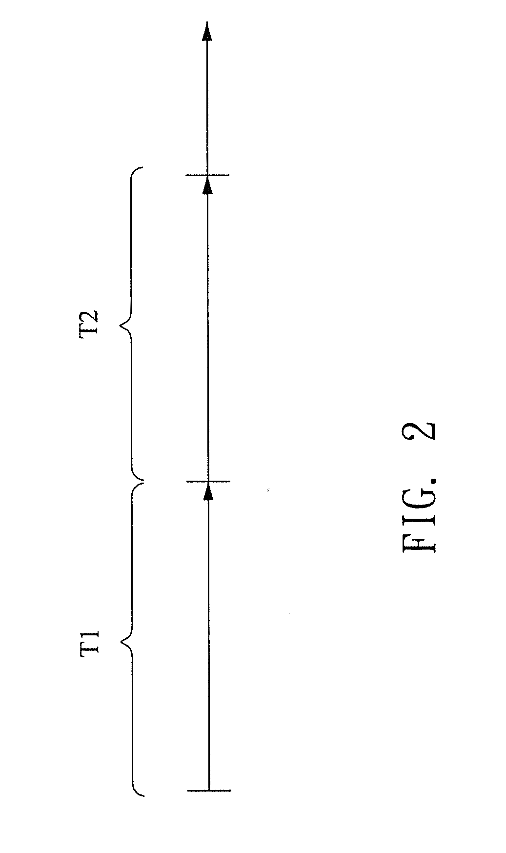
[0016]The electric appliance load 3 is connected to the power supply 2 through a power supply loop L. The electric appliance load 3 can be operated in operation mode T1 or power saving mode T2 (As shown in FIG. 2). The operation mode T1 defined in this specification includes the electric appliance load 3 in operation mode, such as in operation status, standby mode, and etc. When the electric appliance load 3 is operated in operation mode, it consumes power more than that in standby mode. The power saving mode T2 defined in this specification includes the electric appliance load 3 in non-operation mode, ...


PUM


Abstract

A saved power measuring circuit comprises a control unit, a clock signal generating circuit connected to the control unit for generating a clock signal to the control unit, a power consumption measuring circuit connected to a power supply loop for measuring the power consumption of an electric appliance load operated in operation mode, a power consumption memory unit connected to the control unit for memorizing the power consumption, a break loop status signal generating circuit for generating a break loop status signal to the control unit. When the control unit receives the break loop status signal generated from the break loop status signal generating circuit, it calculates saved power of the electric appliance load in power saving mode according to the power consumption and the lasting time after receiving the break loop status signal.

Description

FIELD OF THE INVENTION[0001]The present invention relates to a power measuring circuit, and in particular to a saved power measuring circuit.DESCRIPTION OF THE RELATED ART[0002]In the electrical technology of prior art, if users want to know the information about power consumption of an electric appliance, a specific electric instrument or a traditional multi-meter is generally used for practically measuring. Taking home-used plug for example, a multi-meter or a voltmeter is usually used to measure voltage condition. First of all, users need to correctly adjust the meter to AC voltage status, and then carefully insert two probes into sockets to measure voltage condition. Another example is that if users want to know current value of a home-used steam cooker, usually another ampere meter (i.e. single-hook type meter) is needed for measuring current value. These measuring methods are only realizable for those who are familiar with electric engineering background knowledge or those who...

Claims


Application Information

Patent Timeline
IPC IPC(8): G01R21/00G06F19/00
CPCG01R21/133
Inventor LIU, YING-CHANG
Owner PRODIGIT ELECTRONICS
Why Eureka
Try Eureka