Adjustable Support Insulator for a High-Voltage Long-Distance Transmission Line

a long-distance transmission line and adjustable technology, applied in the direction of insulated conductors, flat/ribbon cables, cables, etc., can solve the problems of enlarged dimensions of long-distance transmission lines, achieve simple adjustment capability, reduce production costs, and simplify the process of laying the inner conductor

Active Publication Date: 2012-07-05
LAPP INSULATOR GMBH & CO KG
View PDF8 Cites 9 Cited by
  • Summary
  • Abstract
  • Description
  • Claims
  • Application Information

AI Technical Summary

Benefits of technology

[0008]In this case, the invention is in general terms based on the approach that the laying of the inner conductor in the interior of the basing tube is associated with not inconsiderable problems. In this case, on the one hand, a minimum distance must be maintained between the inner conductor and the casing tube in order to avoid voltage flashovers in the interior of the line. In other words the inner conductor should run approximately centrally in the casing tube, or, in the case of a round tube, should be laid coaxially with respect to it, thus ensuring a constant separation from the surrounding casing tube. In this case, the invention has identified that an adjustment capability for the inner conductor considerably simplifies the laying of the long-distance transmission line and makes a considerable contribution to improving safety, since it is now possible to compensate for manufacturing tolerances during assembly, or to take adequate account of curved laying sections.
[0009]Especially also in the case of a junction to larger diameters of the casing tube as are required in particular when inert gas is dispensed with for cost reasons, an adjustment capability for the inner conductor is desirable in order to prevent a voltage flashover in air. The junction between the inert gas and air in this case admittedly has the disadvantage that the long-distance transmission line has enlarged dimensions overall. However, to a certain extent, an air-insulated tubular line such as this is maintenance-free, since there is no need whatsoever to prevent inert gas from emerging. To this extent, a long-distance transmission line such as this can be laid over long distances, even through rough terrain, while nevertheless ensuring transmission reliability. In this case, there is neither any need for overhead line pylons nor to regularly keep a safety lane clear of subsequently growing vegetation, with respect to the voltage-carrying overhead line. For this purpose in particular, simplification of the laying process is particularly desirable, in order to further reduce costs.
[0011]In one advantageous development of the long-distance transmission line, the holding insulators are essentially in the form of rods and are each screwed to the inner conductor and to the casing tube via a threaded connection, with the threaded connections having an opposite rotation sense with respect to one another on the inner conductor and on the casing tube. This provides a surprisingly simple adjustment capability for the distance between the inner conductor and the casing tube. Depending on the rotation sense of the holding insulator about its longitudinal axis, this is either screwed at both ends into the attachment points on the inner conductor and in the casing tube, or is screwed out from the attachment points. Simple rotation of the holding insulator which is in the form of a rod to this extent makes it possible to align the position of the inner conductor with respect to the casing tube exactly and as desired. At the threaded connections, the holding insulator is screwed in as envisaged as far as a nominal position, in particular as indicated by appropriate marking, and manufacturing tolerances, curvatures or the like are then compensated for by screwing further in or back. This considerably simplifies the process of laying the inner conductor in the casing tube. The mirror-image symmetrical configuration of the two metal fittings additionally reduces the production costs for the holding insulator.
[0012]In principle, the holding insulators may also be in the form of ceramic insulators. In order to achieve good insulation with robust mechanical strength at the same time, the holding insulators are, however, each preferably in the form of so-called composite insulators having a glass fiber stalk which is essentially in the form of a rod, and having an insulating compound which is applied thereto and in particular is composed of silicone rubber. The glass-fiber stalk provides the required mechanical robustness. In particular this is also insensitive to twisting as required for the abovementioned adjustment. The insulation capability is enhanced by the insulating compound applied to the stalk. Furthermore, in this case, the contamination tendency in respect to foreign particles, moisture or the like can in this case be improved by an appropriate chemical composition of the insulating compound.
[0015]The threads on the metal fittings may each be either in the form of internal threads or external threads. However, since an internal thread additionally necessitates connection points in the form of thread pins on the inner conductor side and on the casing tube side, it is preferable for the fitting ends to be in the form of threaded rods or threaded bolts. Since threaded rods enter the threaded holes on the inner conductor and on the casing tube, projecting edges and corners at the attachment point can be avoided, which is advantageous from the point of view of corona discharges.
[0020]The provision of holding sockets in which the threaded connections are held makes it possible to avoid corners and edges, which are disadvantageous for voltage or corona discharges. If the threaded connections enter the holding sockets, then this results in a relatively smooth junction in the interior of the long-distance transmission line between the inner walls of the inner conductor, and of the casing tube, which run in the longitudinal direction, with respect to the holding insulators, which are screwed in transversely.

Problems solved by technology

The junction between the inert gas and air in this case admittedly has the disadvantage that the long-distance transmission line has enlarged dimensions overall.

Method used


Image

  • Adjustable Support Insulator for a High-Voltage Long-Distance Transmission Line
  • Adjustable Support Insulator for a High-Voltage Long-Distance Transmission Line
  • Adjustable Support Insulator for a High-Voltage Long-Distance Transmission Line

Examples


Embodiment Construction

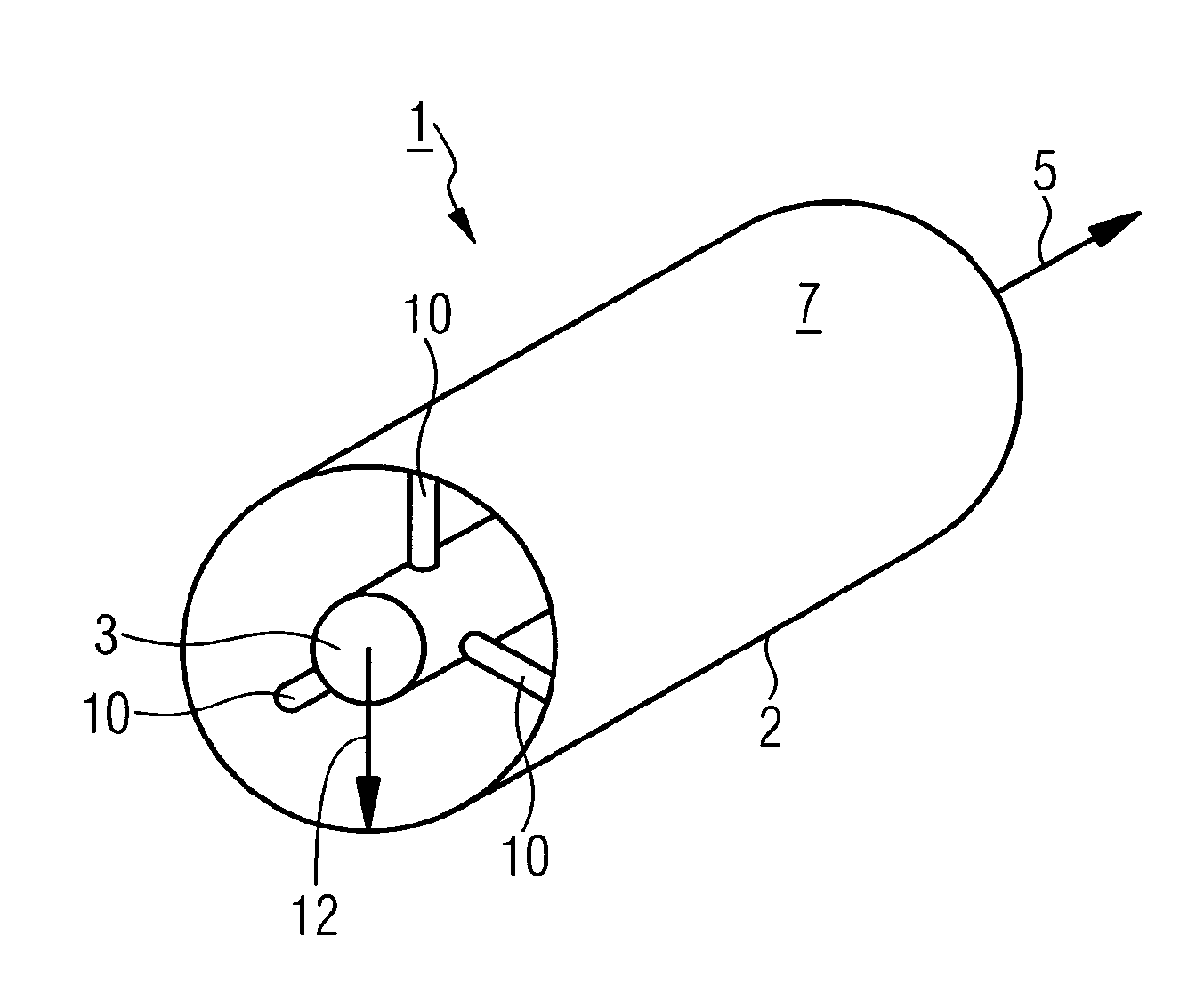
[0038]FIG. 1 schematically illustrates a section of a long-distance transmission line 1 in which a cylindrical, solid inner conductor 3 is laid in the interior of a hollow-cylindrical casing tube 2. In this case, the inner conductor 3 is laid coaxially with respect to the casing tube 2. Alternatively, the inner conductor is in the form of a tubular conductor. The long-distance transmission line 1 extends overall along a longitudinal direction 5. The figure in this case shows a single subpiece 7, with a multiplicity of subpieces 7 being placed adjacent to one another, overall, in the longitudinal direction 5, for example by screw connection or welding, to form the long-distance transmission line 1.

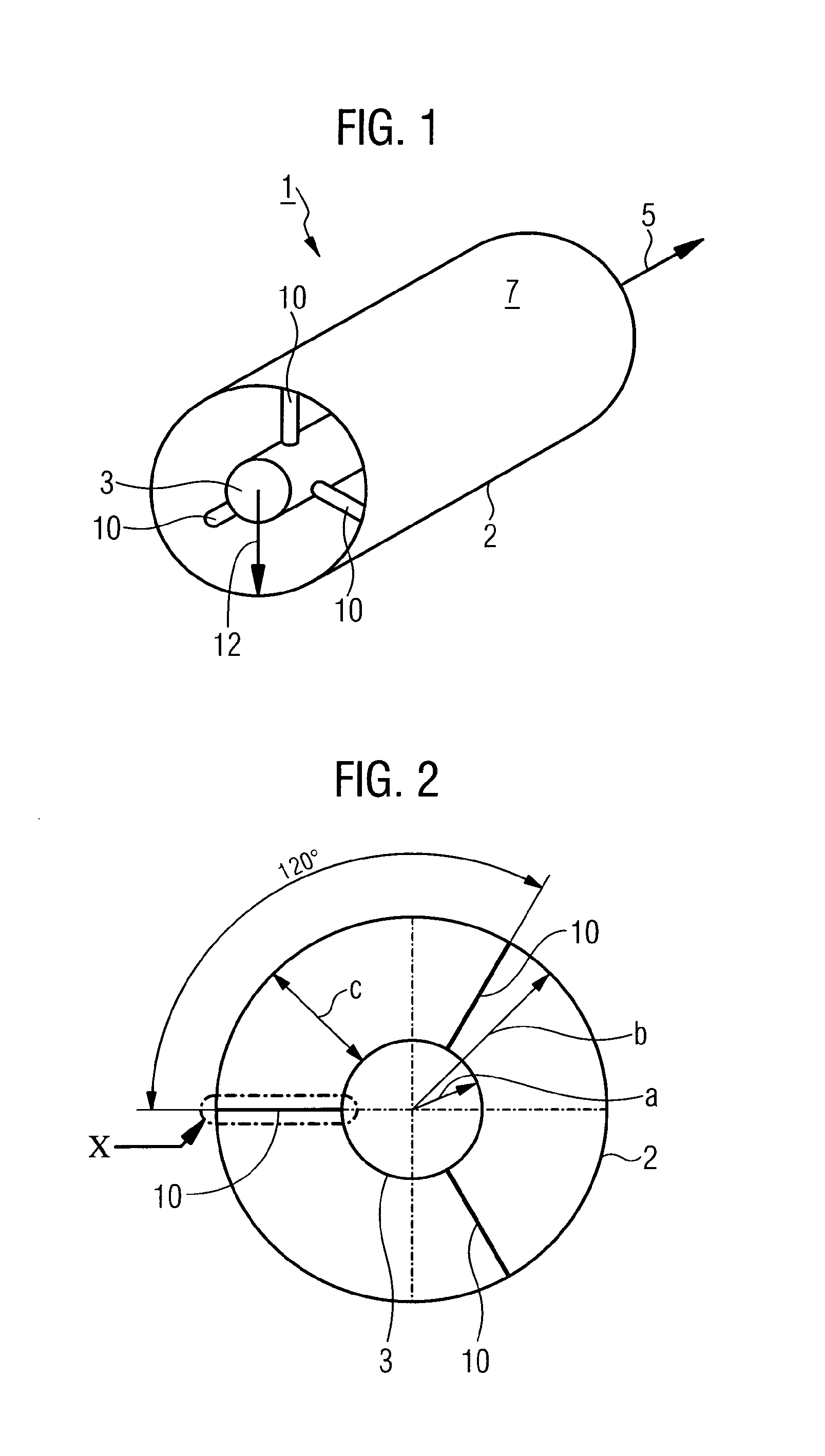
[0039]Both the casing tube 2 and the inner conductor 3 are manufactured from aluminum or some other electrically highly conductive light metal alloy. At regular intervals along the longitudinal direction 5, the inner conductor 3 is held by means of in each case three holding insulators 10 i...


PUM

PropertyMeasurementUnit
diameteraaaaaaaaaa
DC voltageaaaaaaaaaa
thicknessaaaaaaaaaa

Abstract

The invention relates to a long-distance line for high voltage, having an outer jacket pipe extending in a longitudinal direction, having an inner conductor led in the interior of the jacket pipe in parallel to the longitudinal direction, and having a number of mounting insulators, by means of which the inner conductor is held on the jacket pipe at a distance therefrom transverse to the longitudinal direction, and a correspondingly embodied mounting insulator. The mounting insulators serve for adjusting the distance between the inner conductor and the jacket pipe. The long-distance transmission line is particularly air insulated in design. The mounting insulators allow simple assembly and installation of the inner conductor.

Description

FIELD OF THE INVENTION[0001]The invention relates to a long-distance transmission line for high voltage having an outer casing tube which extends in a longitudinal direction, having an inner conductor which is routed parallel to the longitudinal direction in the interior of the casing tube and having a number of holding insulators, via which the inner conductor is held transversely with respect to the longitudinal direction on the casing tube and at a distance from it. The invention also relates to a holding insulator for separated attachment of an inner conductor in the interior of a casing tube, in particular for a correspondingly designed long-distance transmission line.BACKGROUND OF THE INVENTION[0002]By way of example, a long-distance transmission line of the abovementioned type is known from the article “Gasisolierter Rohrleiter (GIL) für Hochspannungsübertragungen” [Gas-insulated tubular conductor for high-voltage transmissions], Josef Kindersberger, IEEE Joint IAS / PELS / IES a...

Claims


Application Information

Patent Timeline
Patent Type & Authority Applications(United States)
IPC IPC(8): H02G3/04H01B17/16
CPCH01B9/065H01B17/14H01B12/00H02G5/066
Inventor SEIFERT, JENS
Owner LAPP INSULATOR GMBH & CO KG
Why Eureka
Try Eureka