Wireless control of laryngoscope system

a technology of laryngoscope and wireless control, which is applied in the direction of electric controllers, ignition automatic control, instruments, etc., can solve the problems of inability to provide oxygen to patients, death or injury, and the procedure is usually quick and uneventful, and achieves convenient use, convenient use, and convenient use.

Active Publication Date: 2012-07-05
DILON TECH
View PDF57 Cites 5 Cited by
  • Summary
  • Abstract
  • Description
  • Claims
  • Application Information

AI Technical Summary

Benefits of technology

[0007]It is an object of the invention to provide an inexpensive, sanitary, easy to use laryngoscope system that may be used in all situations, including most difficult intubations in the most challenging environments.
[0018]In another aspect of the present invention, a user using the ejection element may eject the sheath without touching the sheath.

Problems solved by technology

When performed by an experienced practitioner, the procedure is usually quick and uneventful.
However, even in the hands of well skilled individuals, there is still an unacceptable number of occurrences in which placement of the endotracheal tube is difficult or impossible resulting in an inability to provide the patient with oxygen leading to death or injury.
Difficulty in placing the endotracheal tube may be due to trauma, abnormal anatomy, disease processes or for unknown and unpredictable reasons.
Over the years, there have been many attempts to improve upon the design of the original laryngoscope, but those attempts have been largely unsuccessful as evidenced by the continued use today of virtually the same device developed in the 1940's.
However, these devices are expensive and often inconvenient to use.
Moreover, prior art devices still fail to offer a solution to the difficult intubations in which a bougie is necessary.

Method used


Image

  • Wireless control of laryngoscope system
  • Wireless control of laryngoscope system
  • Wireless control of laryngoscope system

Examples


Embodiment Construction

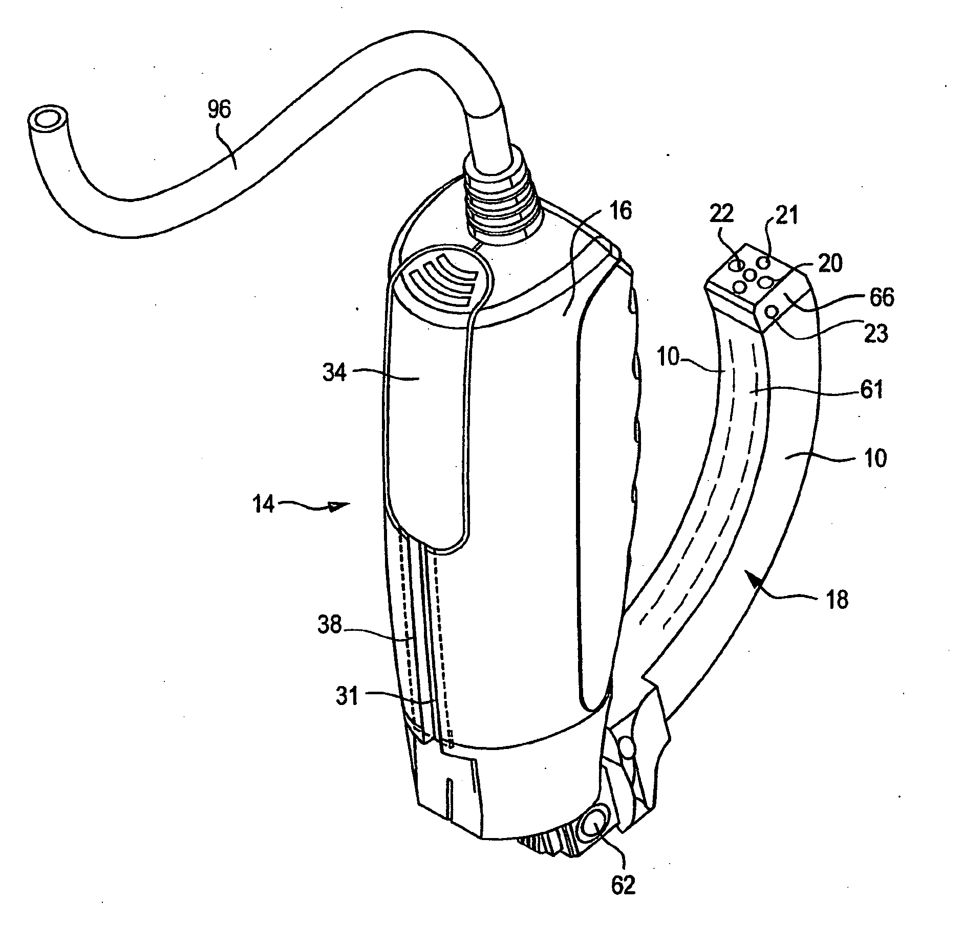
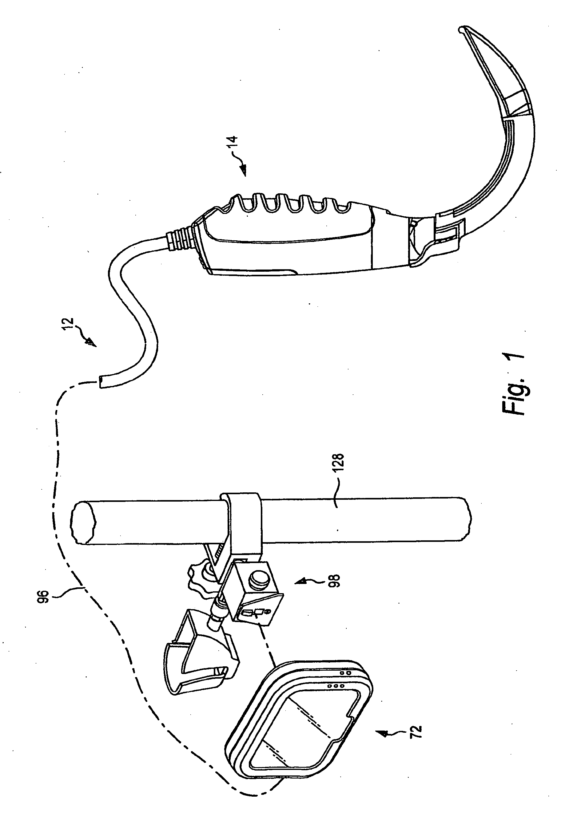
[0037]Referring to FIGS. 1-15 there is shown a laryngoscope system 12 of the present invention. This laryngoscope system 12 is generally comprised of a laryngoscope 14, a display unit 72, and an IV pole attachment 98 capable of being coupled to an IV pole 128.

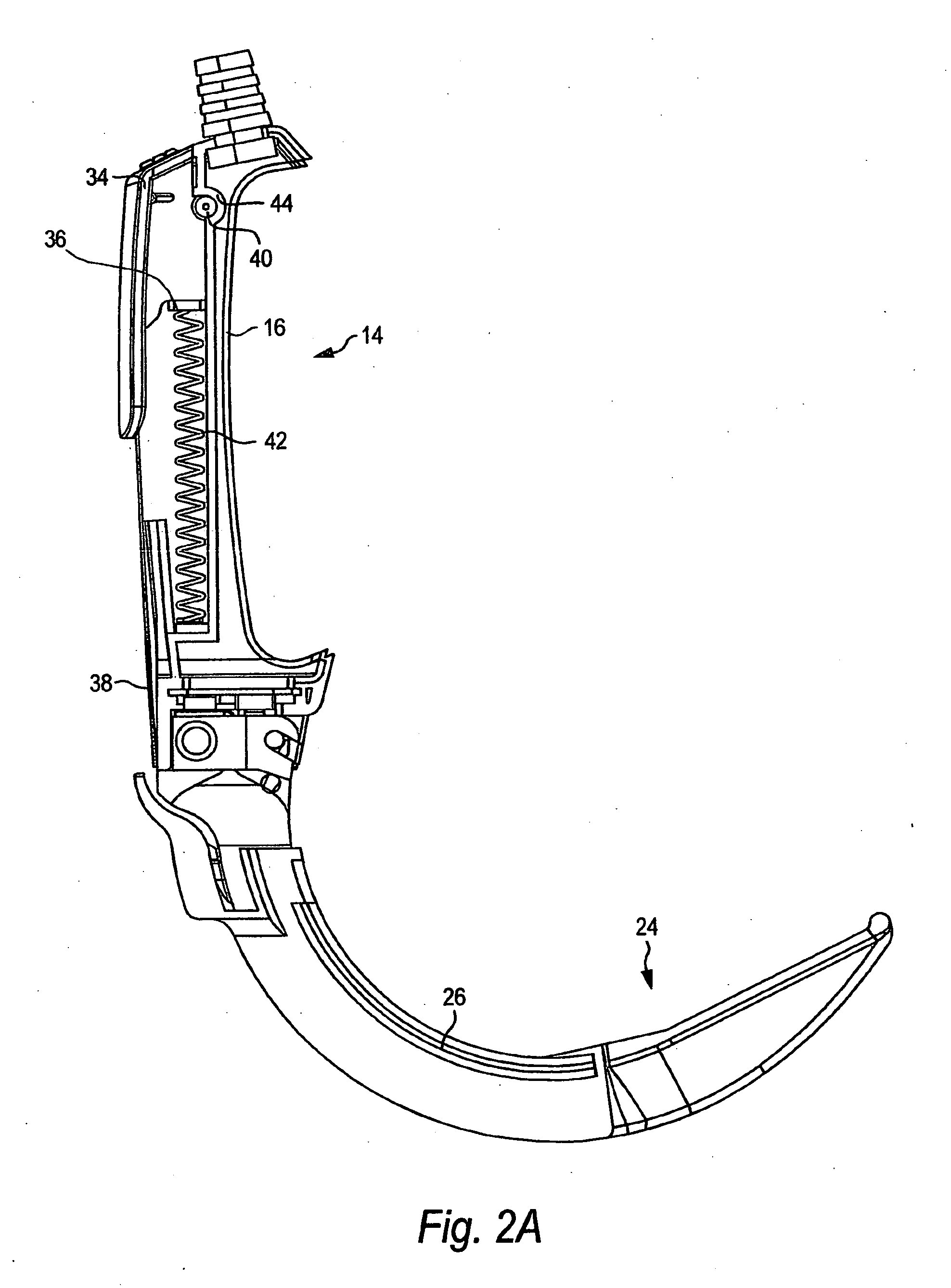
[0038]Referring to FIGS. 1-6, the laryngoscope 14 of the present invention comprises a handle 16, a curved blade or arm 18, a light 20, a camera 22, and a disposable sheath 24. The handle 16 of the laryngoscope 14 has a curved arm 18 attached. In one aspect of the present invention, the arm 18 is removably coupled to the handle 16. Slideably coupled to the arm 18 is a sheath 24 which snaps into place at a coupling point 68 (FIG. 3). In the preferred embodiment, this sheath 24 is formed from plastic and is at least partially clear so as to allow light emitted from the light 20 to pass through it. Referring to FIG. 6, in the preferred embodiment, the sheath 24 is comprised of a transparent window 28. The sheath 24 has one or more...


PUM


Abstract

A Laryngoscope system for controlling and monitoring characteristics associated with airway management and a remote access unit continuously interfacing through instant wireless private direct connectivity to a laryngoscope. The system also includes a plurality of sensors and controllers that measure and control characteristics and provide the remote unit with measurements and control results. In other aspects, the laryngoscope and display unit are sensitive to movement and may power on and off with motion or absence of motion. In another aspect, the laryngoscope is capable of wirelessly communicating with the screen for command and control of the Laryngoscope and laryngoscope system.

Description

CROSS REFERENCE TO RELATED APPLICATIONS[0001]This application is a divisional which claims the benefit of US Published Application US 2010 / 0249513 A1 filed on Mar. 31, 2010, which claims the benefit of PPA No. 61 / 165,091, filed on Mar. 31, 2009 referenced by incorporation herein which claims the benefit of PPA 61 / 427,010 filed Jan. 28, 2011 by the present inventor.DESCRIPTION OF THE PRIOR ART[0002]Over 20 million intubation procedures are performed each year in the United States either as a routine part of surgery or in emergency situations resulting from trauma, cardiopulmonary arrest or other disease processes. In an intubation procedure, it is necessary to insert an endotracheal tube (ET tube) in order to maintain a patient's respiratory function. The tube is inserted into a patient's trachea via either the mouth or nasal tract so that the airway remains open and oxygen reaches the patient's lungs.[0003]Practitioners use an instrument known as a laryngoscope to help in the placem...

Claims


Application Information

Patent Timeline
Patent Type & Authority Applications(United States)
IPC IPC(8): G05B11/01
CPCA61B1/00052A61B1/00101A61B1/00105A61B1/267A61M2209/082A61M2205/3569A61M2205/3592A61M2205/502A61M16/0488A61B1/05A61B1/0676
Inventor TYDLASKA, JAY (JASON)SHEPPARD, AMY
Owner DILON TECH
Why Eureka
Try Eureka