Device for the thermal connection of an energy storage

a technology for thermal connection and energy storage, which is applied in the direction of sustainable manufacturing/processing, final product manufacturing, lighting and heating apparatus, etc. it can solve the problems of damage to energy storage, low gravimetric and volumetric energy density of cooling apparatus, gravimetric and volumetric energy density, etc., and achieve optimal battery operation and keep the temperature difference in the cell low

Inactive Publication Date: 2012-07-05
MAHLE INT GMBH
View PDF7 Cites 36 Cited by
  • Summary
  • Abstract
  • Description
  • Claims
  • Application Information

AI Technical Summary

Benefits of technology

[0017]In this manner, it is possible to uniformly cool or heat the cells integrated in the battery and to thereby keep the temperature difference in the cells as low as possible.
[0018]The fact that all of the cells are cooled uniformly, i.e., all of the cells are at the same temperature level, is important for an optimal operation of the battery. The temperature level of the cells influences the service life as well as the performance. It is also important to keep the temperature difference inside the cells, caused by the cooling, as low as possible. This can be ensured by means of the approach according to the invention.
[0019]Advantageously, a use of thick cooling fins or the use of a fluid between the cells is not necessary according to the invention in order to achieve a suitable temperature control or a minimization of a maximum temperature difference on the surface of a battery cell.

Problems solved by technology

Temperatures higher than 50° C. permanently damage the energy storage.
Thick cooling fins result in a low gravimetric and volumetric energy density of the cooling apparatus.
In the case of the cooling fins flowed through by fluid, disadvantages occur in the gravimetric and volumetric energy density, since due to the production possibilities and the permissible pressure loss in the overall construction, the fin thicknesses and the coolant channels cannot be selected to be as small as desired.
Moreover, there is also the problem of tightness in the connections and the uniform distribution of the cooling fluid.

Method used


Image

  • Device for the thermal connection of an energy storage
  • Device for the thermal connection of an energy storage
  • Device for the thermal connection of an energy storage

Examples


Embodiment Construction

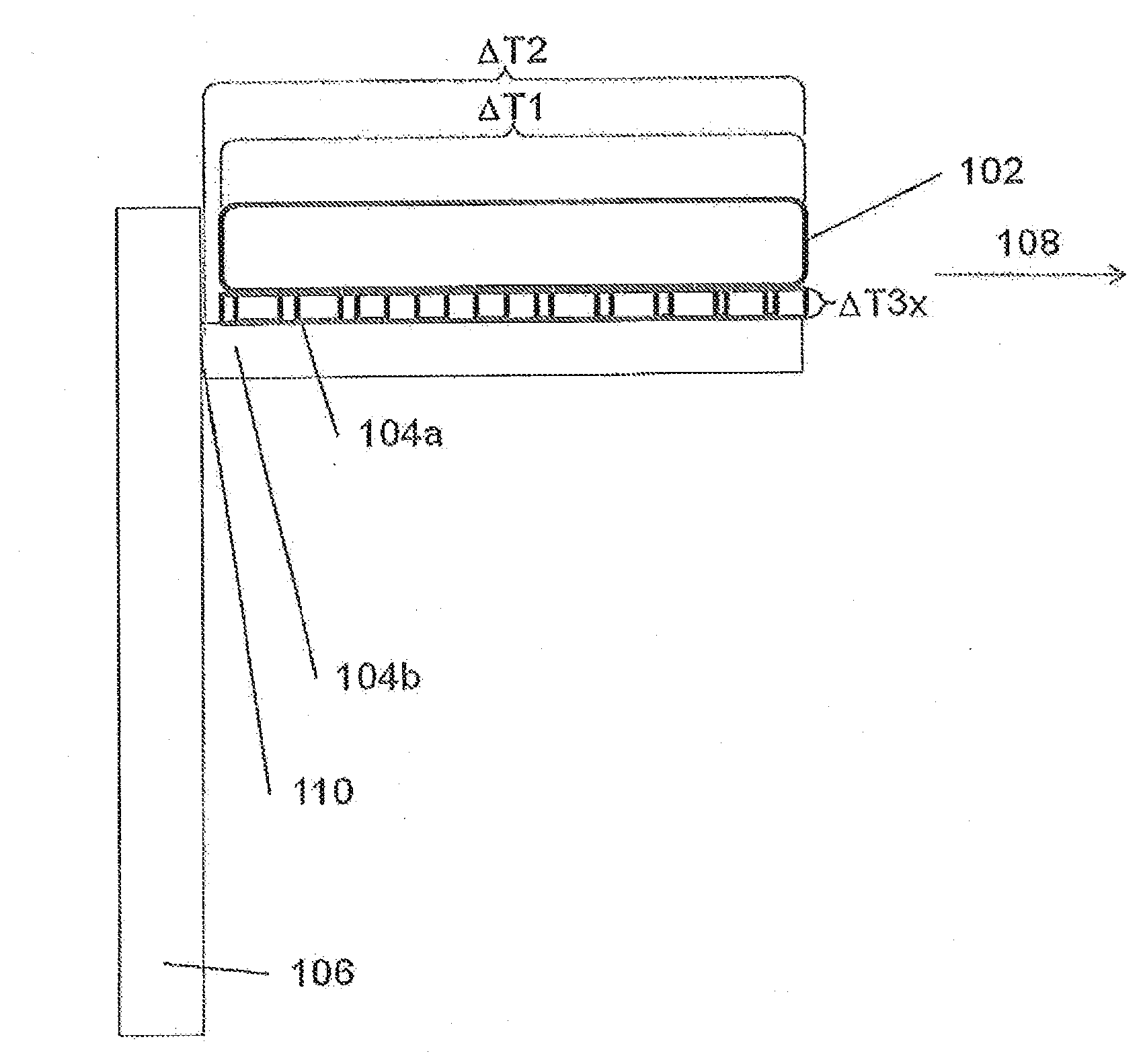
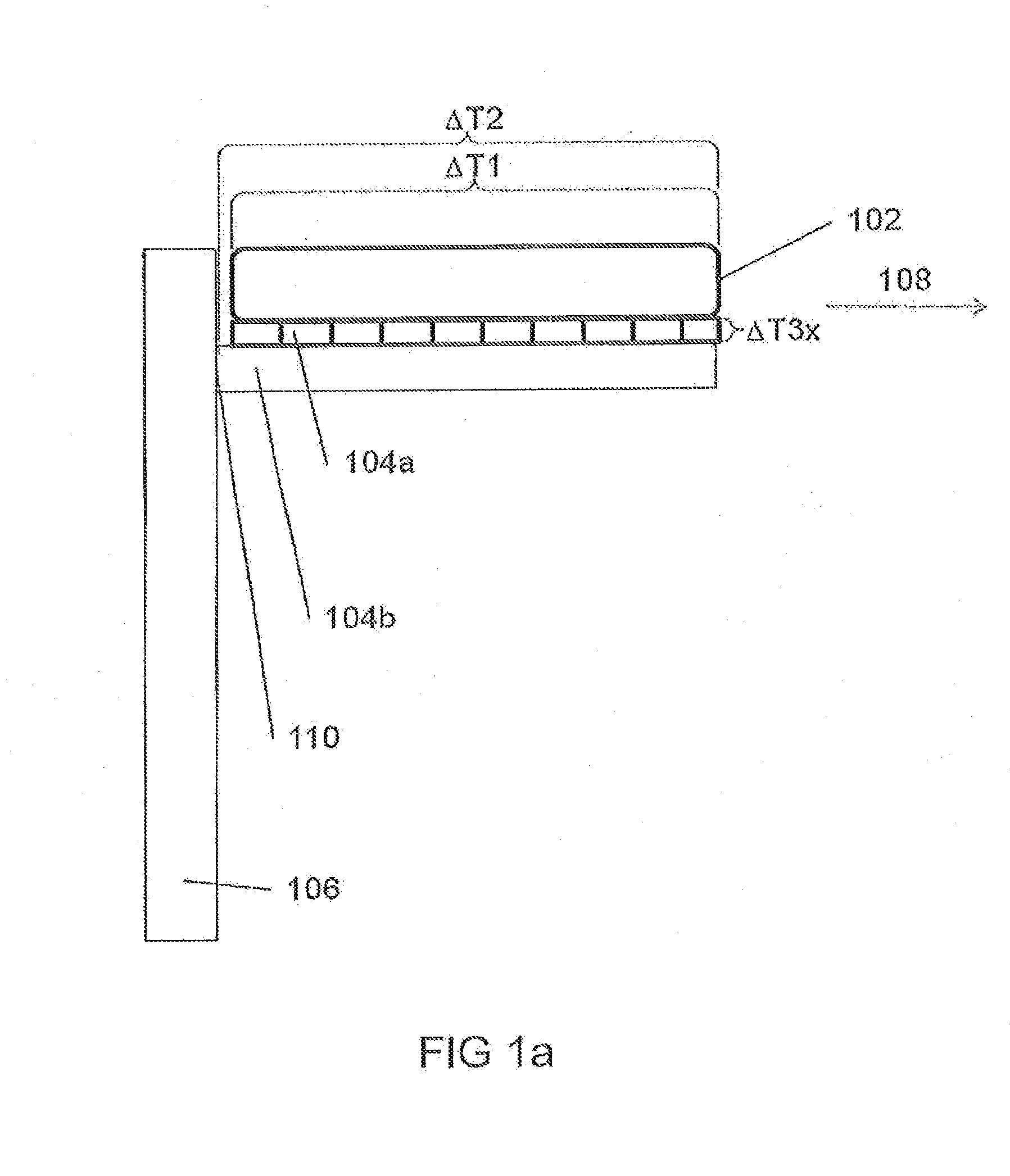
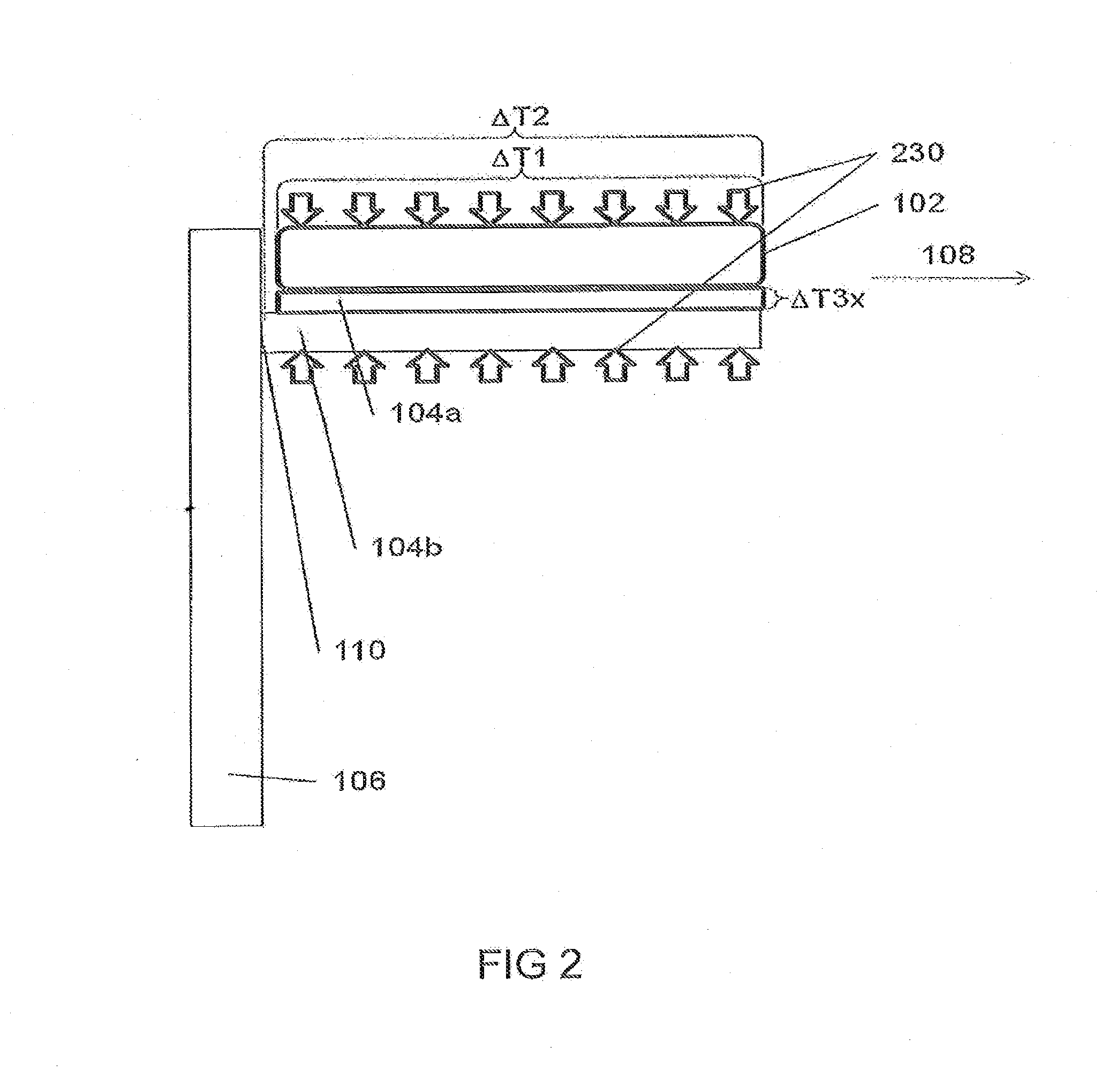
[0043]In the following description of the preferred exemplary embodiments of the present invention, the same or similar reference numbers are used for the elements that are shown in the various drawings and that act in a similar manner, a repeated description of these elements being omitted.

[0044]In a heat transfer between battery cell and cooling fin, with an areal thermal connection, uniform over the height, of a cooling fin to a cell outside surface, the heat flow flows over the entire cell height up to the heat sink at the base of the cooling fin (=cell base). Naturally, a considerable temperature difference results in the cooling fin as a result of the height of the cooling fin and depending on its thickness. The temperature difference over the cell height, which is labeled ΔT1, is also correspondingly high.

[0045]According to the invention, a variable heat transfer between the battery cell and cooling fin is provided. To this end, the heat transfer is changed at a corresponding...


PUM

PropertyMeasurementUnit
heat-conducting propertyaaaaaaaaaa
energyaaaaaaaaaa
contact resistancesaaaaaaaaaa

Abstract

A device for thermal connection of an energy store to a cooling plate and/or a contact element, and a cooling plate on a contact element and/or a fluid is provided. The device for thermal connection has a first region having a first heat transfer property and at least one other region having another heat transfer property, wherein the first region and the at least one other region are arranged next to one another in relation to the heat transfer surface.

Description

[0001]This nonprovisional application is a continuation of International Application No. PCT / EP2010 / 053870, which was filed on Mar. 25, 2010, and which claims priority to German Patent Application Nos. DE 10 2009 014 954.6, which was filed in Germany on Mar. 30, 2009, and to DE 10 2009 035 088.8, which was filed in Germany on Jul. 28, 2009, and which are all herein incorporated by reference.BACKGROUND OF THE INVENTION[0002]1. Field of the Invention[0003]The present invention relates to a device for the thermal connection of an energy storage and / or a cooling plate a device for the thermal connection of a plurality of cooling fins to a cooling plate, to an energy storage device and to a device for the thermal connection of a fluid.[0004]2. Description of the Background Art[0005]Powerful energy storage devices, such as, for example Li ion or NiMH accumulator batteries or super caps, are used in modern hybrid electric vehicles (HEV) or electric vehicles (EV). Heating occurs with these ...

Claims


Application Information

Patent Timeline
Patent Type & Authority Applications(United States)
IPC IPC(8): H01M10/50F28F1/10H05K7/20F28F7/00
CPCB60K1/04B60K2001/005B60L11/1874H01M10/0413H01M10/5004Y02T10/705H01M10/5032H01M10/5038H01M10/5053H01M10/5057Y02T10/7005H01M10/5016B60L58/26H01M10/613H01M10/625H01M10/647H01M10/652H01M10/6554H01M10/6556Y02E60/10Y02T10/70Y02P70/50
Inventor HIRSCH, STEFANWIEBELT, ACHINSCHMID, CAROLINEISERMEYER, TOBIASEISELE, MARC-THOMAS
Owner MAHLE INT GMBH
Why Eureka
Try Eureka