Reaction device, heat-insulating container, fuel cell device, and electronic apparatus

a technology of reaction device and heat-insulating container, which is applied in the direction of electrochemical generator, physical/chemical process catalyst, sustainable manufacturing/processing, etc., can solve the problems of difficulty in maintaining temperature difference in reaction device, and achieve large difference in operation temperature

Inactive Publication Date: 2010-10-12
CASIO COMPUTER CO LTD
View PDF13 Cites 0 Cited by
  • Summary
  • Abstract
  • Description
  • Claims
  • Application Information

AI Technical Summary

Benefits of technology

[0007]Therefore, a principal object of the present invention is to provide a heat-insulating container and a reaction device that are able to maintain temperature difference between reaction units in the reaction device that comprises two or more reaction units, and a fuel cell device and electronic apparatus that utilize the reaction device.

Problems solved by technology

Thus, the difference in operation temperature is large.
However, it was difficult to maintain temperature difference in the reaction device, since heat of the reformer propagates and temperature of the vaporizer and the carbon monoxide remover increases.

Method used


Image

  • Reaction device, heat-insulating container, fuel cell device, and electronic apparatus
  • Reaction device, heat-insulating container, fuel cell device, and electronic apparatus
  • Reaction device, heat-insulating container, fuel cell device, and electronic apparatus

Examples


first embodiment

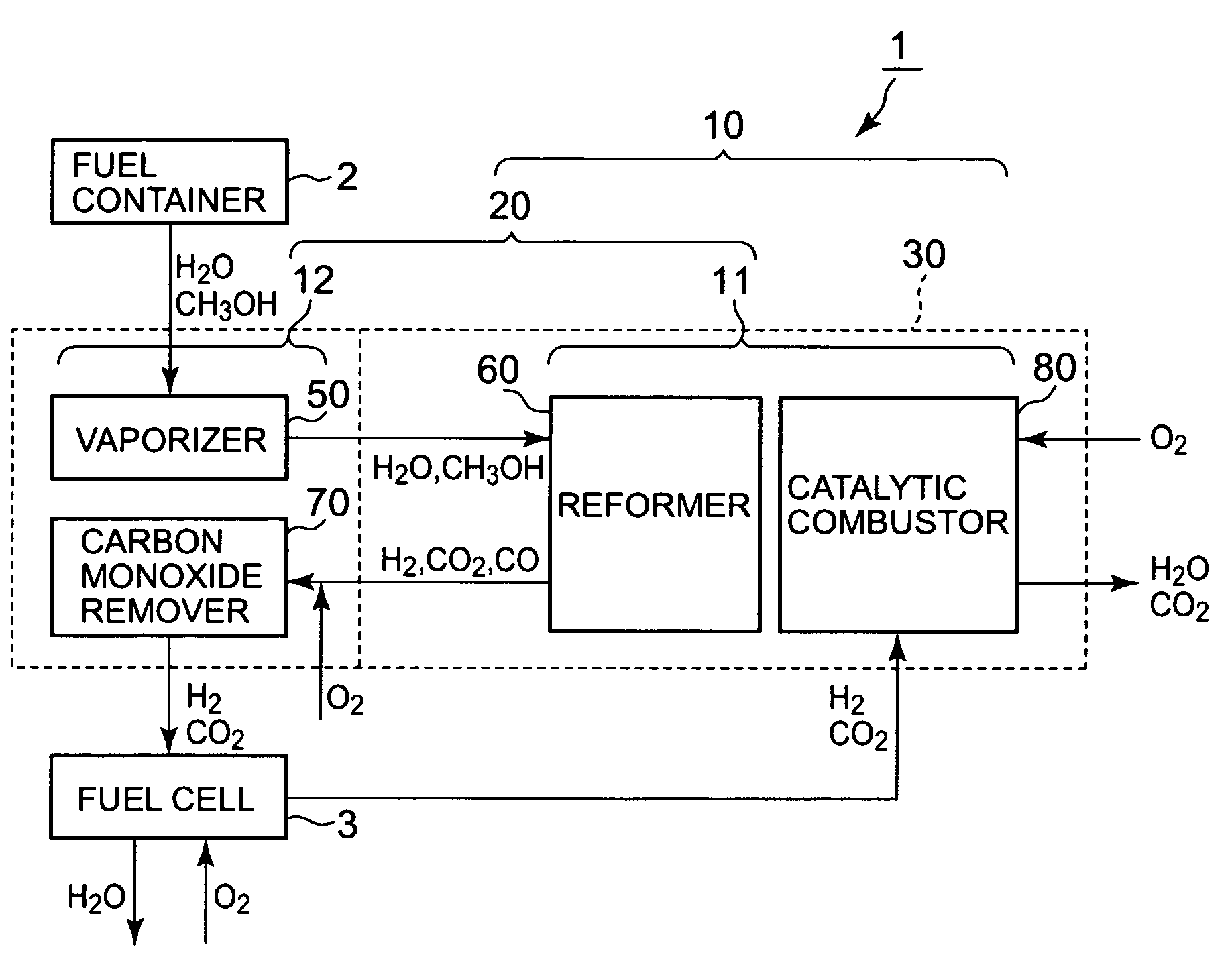
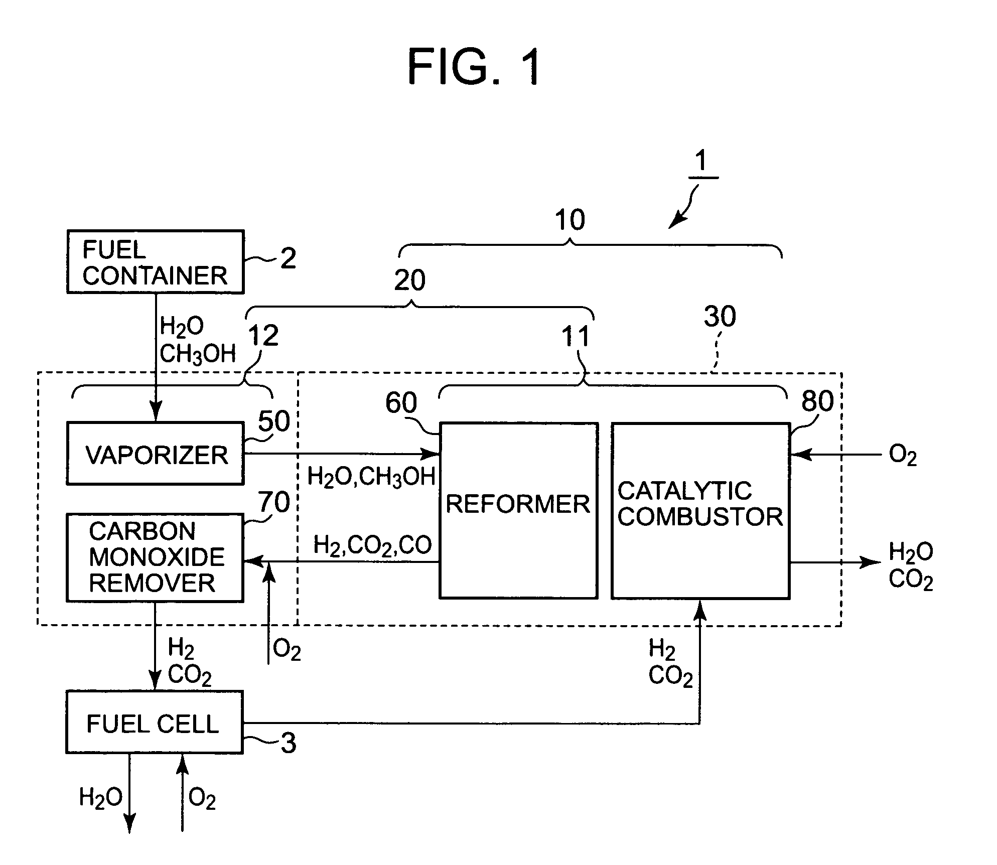
[0084]FIG. 1 is a block diagram of a fuel cell device 1 which is preferably applied with the present invention. The fuel cell device 1 is provided to a lap-top personal computer, a mobile phone, a personal digital assistant (PDA), an electronic notebook, a wrist watch, a digital still camera, a digital video camera, a game apparatus, an amusement apparatus, an electronic calculator, and other kinds of electronic apparatuses, and is used as a power source to operate electronic apparatus main body.

[0085]The fuel cell device 1 is provided with a fuel container 2, a reaction device 10, and a fuel cell 3. As described later, in a case where the reaction device 10 and the fuel cell 3 are housed in the electronic apparatus main body, the fuel container 2 is provided to the electronic apparatus main body detachably, and the fuel container 2 is attached to the electronic apparatus main body, the fuel and water in the fuel container 2 may be supplied to the reaction device 10 by a pump.

[0086]...

modification example 1

[0129]In the aforementioned embodiment, heat releasing portion 40 was provided by setting a heat absorbing film 32b on the heat reflective film 32a. However, as shown in FIG. 9, an opening portion, where base material of the heat-insulating container is exposed, may be formed by not providing the heat reflective film 32a to a portion of a surface of internal wall of the package 31. The opening portion works as the heat releasing portion 41. In this case, the reflectivity of the opening portion is the reflectivity of the package 31.

[0130]Here, in a case where the package 31 is a glass substrate, most of the infrared ray transmits the package 31. Therefore, reflectivity of the opening portion becomes relatively lower compared to that of the portion where the package 31 overlaps with the heat reflective film 32a, where it is not the opening portion.

modification example 2

[0131]Alternatively, as shown in FIG. 10, the heat absorbing film 32b may be provided to the entire surface of the internal wall of the package 31, and the heat reflective film 32a may be provided on the heat absorbing film 32b with some exceptional portion, thus opening portion where the heat absorbing film 32b is exposed may becomes the heat releasing portion 42.


PUM

PropertyMeasurementUnit
temperatureaaaaaaaaaa
pressureaaaaaaaaaa

Abstract

Disclosed is a reaction device that includes a reaction device main body that includes a first reaction unit and a second reaction unit, a container to house the reaction device main body and a first region that corresponds to at least the first reaction unit and a second region that corresponds to the second reaction unit, the first and second regions being provided to the container or internal side of the container. The first reaction unit is set to a temperature higher than that of the second reaction unit, and the first region has a higher reflectivity than that of the second region, with respect to heat ray that is radiated from the reaction device main body.

Description

BACKGROUND OF THE INVENTION[0001]1. Field of the Invention[0002]The present invention relates to a reaction device and a heat-insulating container, in particular, to a reaction device that integrates reactors requiring different operation temperatures such as a vaporizer, a reformer, a carbon monoxide remover, and the like that are used for a fuel cell device, to a heat-insulating container that houses reactors requiring different operation temperatures, and power generation device and electronic apparatus provided with the power generation device that includes the reaction device or the heat-insulating container.[0003]2. Description of the Related Art[0004]Recently, as a power source that is clean and has high energy conversion efficiency, fuel cell that uses hydrogen as fuel is coming in application to car vehicles, portable devices, and the like. Fuel cell is a device that makes fuel and oxygen in the atmosphere react electro-chemically, and generates electric energy from chemica...

Claims


Application Information

Patent Timeline
Patent Type & Authority Patents(United States)
IPC IPC(8): B01J7/00H01M8/06B01J8/00B01J8/04B01J10/00B01J19/00
CPCB01J19/0093B01J19/249C01B3/323C01B3/384H01M8/0618B01J2219/00153B01J2219/00155B01J2219/00783B01J2219/00835B01J2219/00873B01J2219/2453B01J2219/2458B01J2219/2465B01J2219/2467B01J2219/2479B01J2219/2496C01B2203/0233C01B2203/0261C01B2203/044C01B2203/047C01B2203/066C01B2203/0811C01B2203/0822C01B2203/0827C01B2203/085C01B2203/1035C01B2203/1076C01B2203/1211C01B2203/1223C01B2203/1229C01B2203/1247C01B2203/1288C01B2203/169H01M8/0668H01M2250/30Y02E60/50Y02B90/18Y02B90/10Y02P20/10
Inventor NAKAMURA, OSAMUNOMURA, MASATOSHI
Owner CASIO COMPUTER CO LTD
Why Eureka
Try Eureka