Aircraft power architecture

a technology of power architecture and aircraft, applied in the direction of machines/engines, mechanical equipment, transportation and packaging, etc., can solve the problems of high mechanical stress in the connection with the main transmission gearbox, and achieve the effect of reducing the mass of electrical equipment and improving the performance of electrical equipmen

Pending Publication Date: 2021-11-25
SAFRAN HELICOPTER ENGINES
View PDF0 Cites 0 Cited by
  • Summary
  • Abstract
  • Description
  • Claims
  • Application Information

AI Technical Summary

Benefits of technology

[0025]This configuration is made possible by improving the performance of electrical equipment such as a starter / generator, in particular by reducing the mass of the electrical equipment with respect to the power produced (in the case of a generator) or consumed (in the case of an electric motor).
[0026]Moving the accessory gearbox into the first compartment has other advantages. The second compartment containing the gas turbine is considered a “hot zone” of the aircraft, because the temperatures there are high due to the operation of the gas turbine, whereas the first compartment is considered a “cold zone” because it does not contain any components that generate a lot of heat. The partition between the first compartment and the second compartment allows these temperature differences to be maintained.

Problems solved by technology

The installation of the gas turbine in the aircraft responds to a multitude of constraints, particularly in terms of space requirements and keeping the gas turbine in place in the aircraft.
However, in this configuration, the gas turbine is only held in place at one end.
The other end is cantilevered and excess mass can lead to high mechanical stresses in the connection with the main transmission gearbox.

Method used


Image

  • Aircraft power architecture
  • Aircraft power architecture

Examples


first embodiment

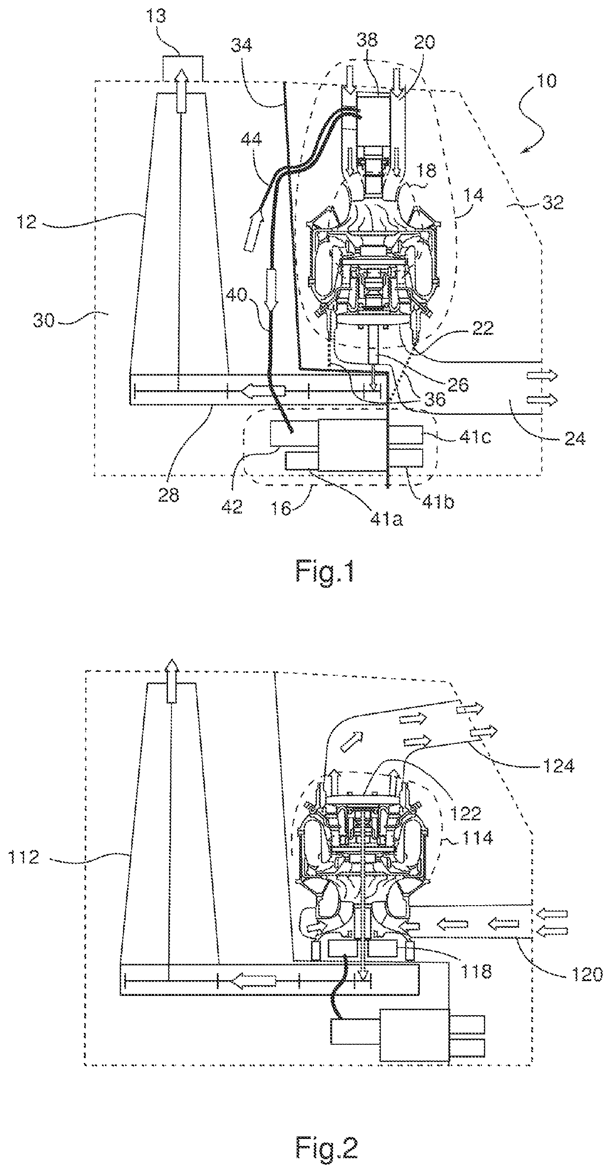
[0056]FIG. 1 schematically represents in partial section a power architecture 10 of an aircraft according to the invention.

[0057]The power architecture 10 comprises in particular a power transmission gearbox 12, a gas turbine 14 and an accessory gearbox 16.

[0058]The power transmission gearbox 12 allows the transmission of energy generated by the gas turbine to a propulsion element rotating around a rotor 13 driven by the power transmission gearbox 12, for example a rotary wing or a propulsion propeller. When the aircraft is a helicopter, the power transmission gearbox is generally referred to as the main transmission gearbox (abbreviated to MGB).

[0059]The gas turbine 14 comprises a gas generator 18, producing in a known way a flow of gas from the compression and combustion of air from an air inlet 20. The gas flow is expanded by a first turbine of the gas generator 18 to allow its own rotation, then in a free turbine 22 of the gas turbine 14. At the free turbine outlet, the exhaust ...

second embodiment

[0070]FIG. 2 schematically represents a partial cross-section of a power architecture according to the invention.

[0071]In this embodiment, the gas turbine 114 is located in an opposite orientation to the first embodiment: the air inlet 120 and the exhaust gas outlet 124 are reversed, and the free turbine 122 is located at the opposite end of the gas turbine 114 with respect to the main transmission gearbox 112. Thus, to set in the gas turbine 114, the power shaft 126 is said to pass through because it passes through the gas turbine 114 to the main transmission gearbox 112. The first electrical machine, here a starter / generator 138, is always located on the air inlet side. The rest of the operation is similar to the power architecture according to the first embodiment of the invention.

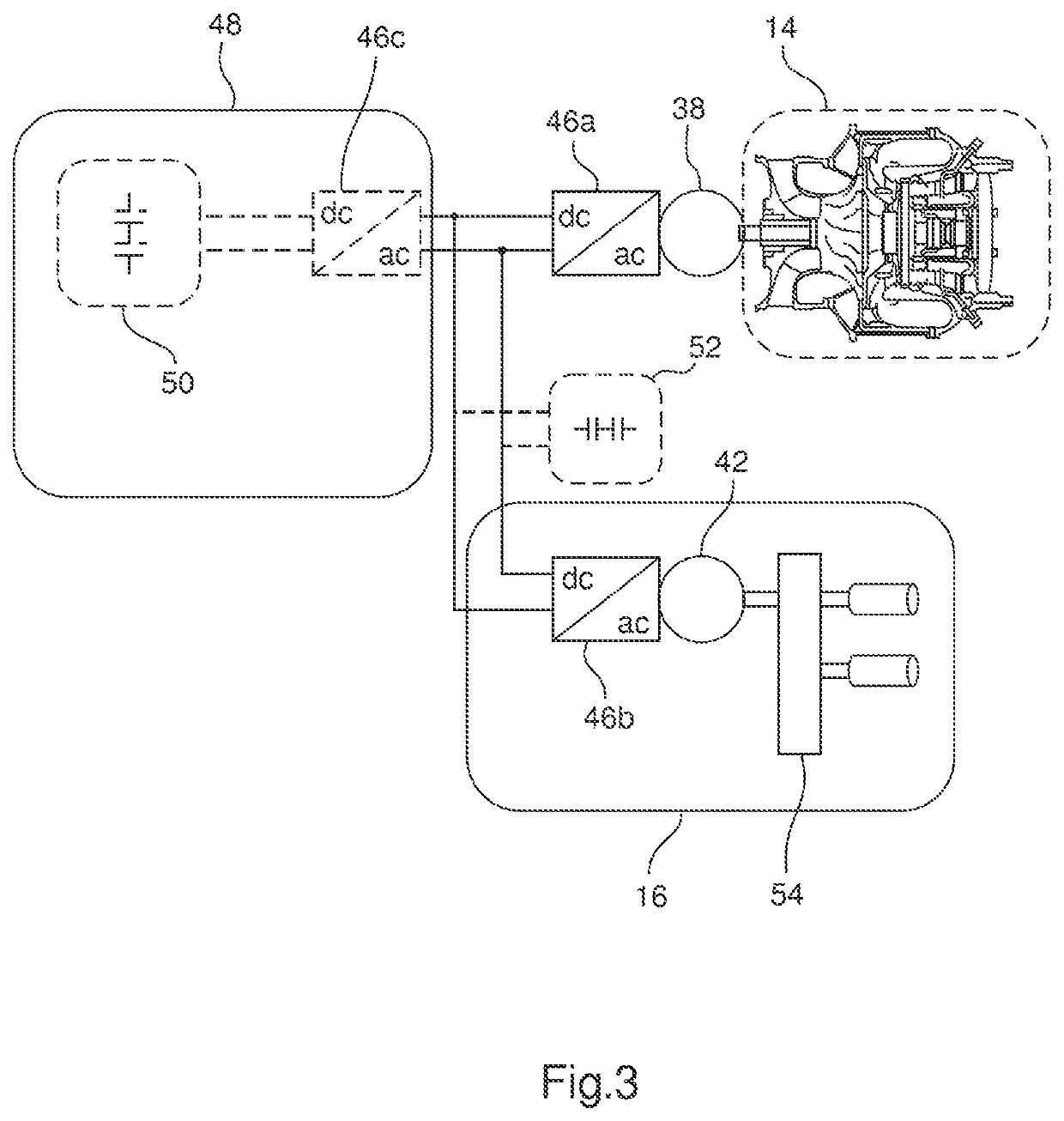
[0072]FIG. 3 schematically represents the electrical architecture of a power architecture according to an embodiment of the invention.

[0073]As shown in FIGS. 1 and 2, the starter / generator 38 recovers a...


PUM


Abstract

The invention relates to an aircraft power architecture comprising a power transmission gearbox (12), located in a first compartment (30), a gas turbine (14), located in a second compartment (32) comprising a gas generator (18) and a free turbine (22) connected to the power transmission gearbox (12) by a power shaft (26) of the gas turbine (14), and an accessory gearbox (16), the gas turbine (14) being set into the main transmission gearbox (12), characterized in that the gas turbine (14) comprises a first electric machine (38), and in that the accessory gearbox (16) is placed in the first compartment (30) and comprises a second electric machine (42) configured to supply energy to the accessory equipment and to receive electrical energy transmitted via the first electric machine (38).

Description

TECHNICAL FIELD OF THE INVENTION[0001]The invention relates to an aircraft power architecture. In particular, the invention relates to an architecture comprising a gas turbine and a power transmission gearbox, for example a main transmission gearbox of a helicopter or another rotary wing aircraft (turboshaft engine architecture), or a transmission gearbox of a fixed wing propeller aircraft (turboprop architecture).BACKGROUND[0002]The prior art comprises in particular the patent applications EP-A1-2 974 964, FR-A1-3 003 514, FR-A1-3 019 219, FR-A1-2 992 630, FR-A1-2 914 697 and FR-A1-2 962 404.[0003]The aircraft power architecture refers to the architecture allowing the production of propulsive energy from the aircraft and its transmission to the propulsion element via a power transmission gearbox, the propulsion element being for example a rotary wing or a propeller.[0004]The power architecture comprises a gas turbine that produces this propulsive energy and transmits it to the powe...

Claims


Application Information

Patent Timeline
Patent Type & Authority Applications(United States)
IPC IPC(8): B64D35/08F02C7/36F02C7/32B64C27/12
CPCB64D35/08F02C7/36B64D27/10B64C27/12F02C7/32B64C27/04B64D33/00B64D35/04B64D2027/026F01D15/10F05D2220/76F02C3/10F05D2220/323F05D2220/329F05D2220/50
Inventor LAFARGUE, OLIVIERKLONOWSKI, THOMAS
Owner SAFRAN HELICOPTER ENGINES
Why Eureka
Try Eureka