
Foley Catheter Collection System

a collection system and catheter technology, applied in catheters, non-surgical orthopedic devices, medical science, etc., can solve the problems of bacterial contamination, high healthcare burden, and high prevalence of foley catheters, and achieve the effects of ensuring the sterility of the drainage system lumen, convenient use, and convenient us

Inactive Publication Date: 2012-07-05
HOLLISTER INCORPORAED
View PDF6 Cites 8 Cited by
  • Summary
  • Abstract
  • Description
  • Claims
  • Application Information

AI Technical Summary

Benefits of technology

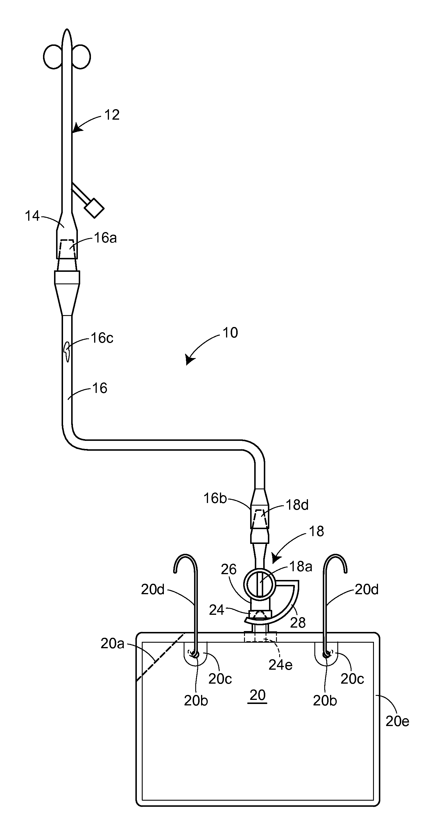
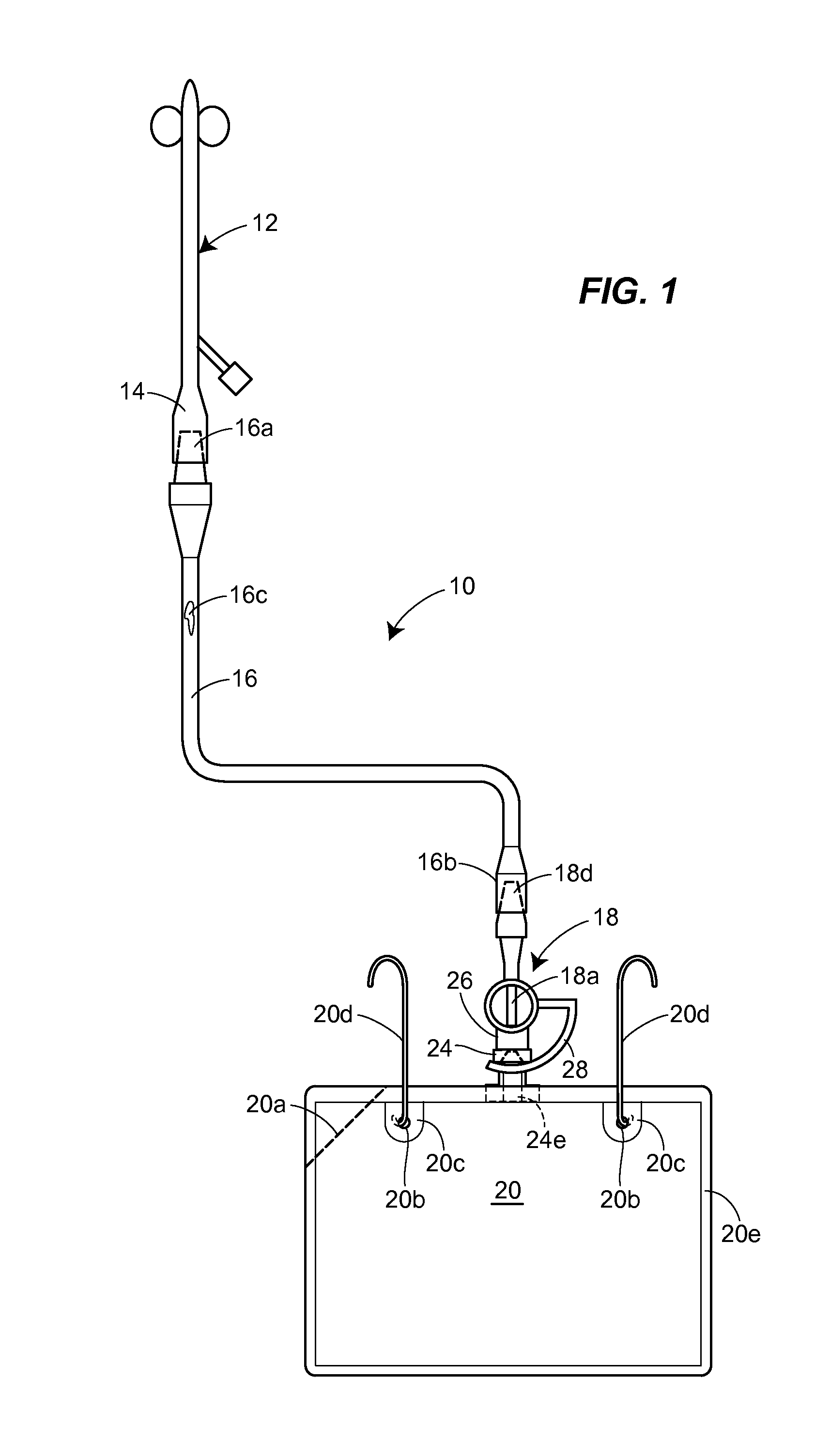
[0008]Accordingly, the present disclosure is directed to a Foley catheter collection system which ensures sterility of the drainage lumen during removal and reconnection of drainage bags. The collection system comprises a tubing element having an end remote from the insertion end of the Foley catheter which includes a drainage valve movable from an open catheter drainage position to a closed position for preventing the flow of urine from the catheter. The collection system also includes a drainage bag having a first connector element associated with the drainage bag and a second connector element associated with the drainage valve.
[0011]Furthermore, the second connector element is designed so that the surfaces that receive the first connector element in mating sealed engagement are easily available for sterilization, e.g. by wiping with a sterilizing fluid or by immersion in a sterilizing fluid.
[0012]The system is intended to be easy to use in a way that ensures sterility of the drainage system lumen. To achieve this end, the drainage bag does not have a conventional drain valve. Instead, it is designed to be inexpensive and disposable after a single use. In this regard, it would have either no drain valve, with for example a tear feature to aid emptying, or else at most an inexpensive, single use drain valve.
[0013]When a drainage bag is full and in need of emptying, the first step is to disengage the connector elements which, as described above, necessarily results in the system drainage lumen being closed. The disconnected bag can now be taken to a toilet and emptied. The used bag is discarded. A new sterilized bag having a first connector element with a sterile mating surface is prepared for use. As noted above, the mating surface of the second connector element is easily sterilized, e.g., by wiping it with or immersing it in a sterilizing fluid. The first and second connector elements are then engaged and the sealing element is moved to a position which opens the drainage valve, allowing communication between the drainage tubing and the collection bag again. The system is now again closed, all parts of the drainage lumen remain sterile, and urine can again drain freely into the new collection bag.

Problems solved by technology

Medical professionals are very aware that infections secondary to the use of Foley catheters represent a significant healthcare burden.
This problem is known to be particularly prevalent during the emptying of urine from the drainage bag.
However, it is also a problem to prevent bacteria from entering the drainage system lumen during transfer of the patient when it may be desirable to have the drainage bag disconnected from the indwelling catheter.
In particular, bacterial contamination often occurs when the connection between the Foley catheter and the drainage tubing is broken and when the drainage bag is drained of urine to allow refilling.
Unfortunately, such highly trained, highly focused nursing care is not available in most patient care settings.
As a result, it is quite common for the lumen of a Foley catheter drainage system to become contaminated.
Once this occurs, it is likely the bacteria will reach the bladder, and the patient will develop a urinary tract infection.

Method used


Image

  • Foley Catheter Collection System
  • Foley Catheter Collection System
  • Foley Catheter Collection System

Examples


Embodiment Construction

[0032]In the illustrations given, and with reference first to FIG. 1, the reference numeral 10 designates generally a Foley catheter collection system in accordance with the present disclosure. The collection system 10 illustrated in FIG. 1 includes a tubing element 16 having a first end 16a for permanent connection to a drain hub 14 of the conventional Foley catheter 12 illustrated in FIG. 1. Further, the tubing element 16 has a second end 16b remote from the first end 16a, and the second end 16b has a drainage valve 18 movable from an open catheter drainage position to a closed position for preventing the flow of urine from the catheter.

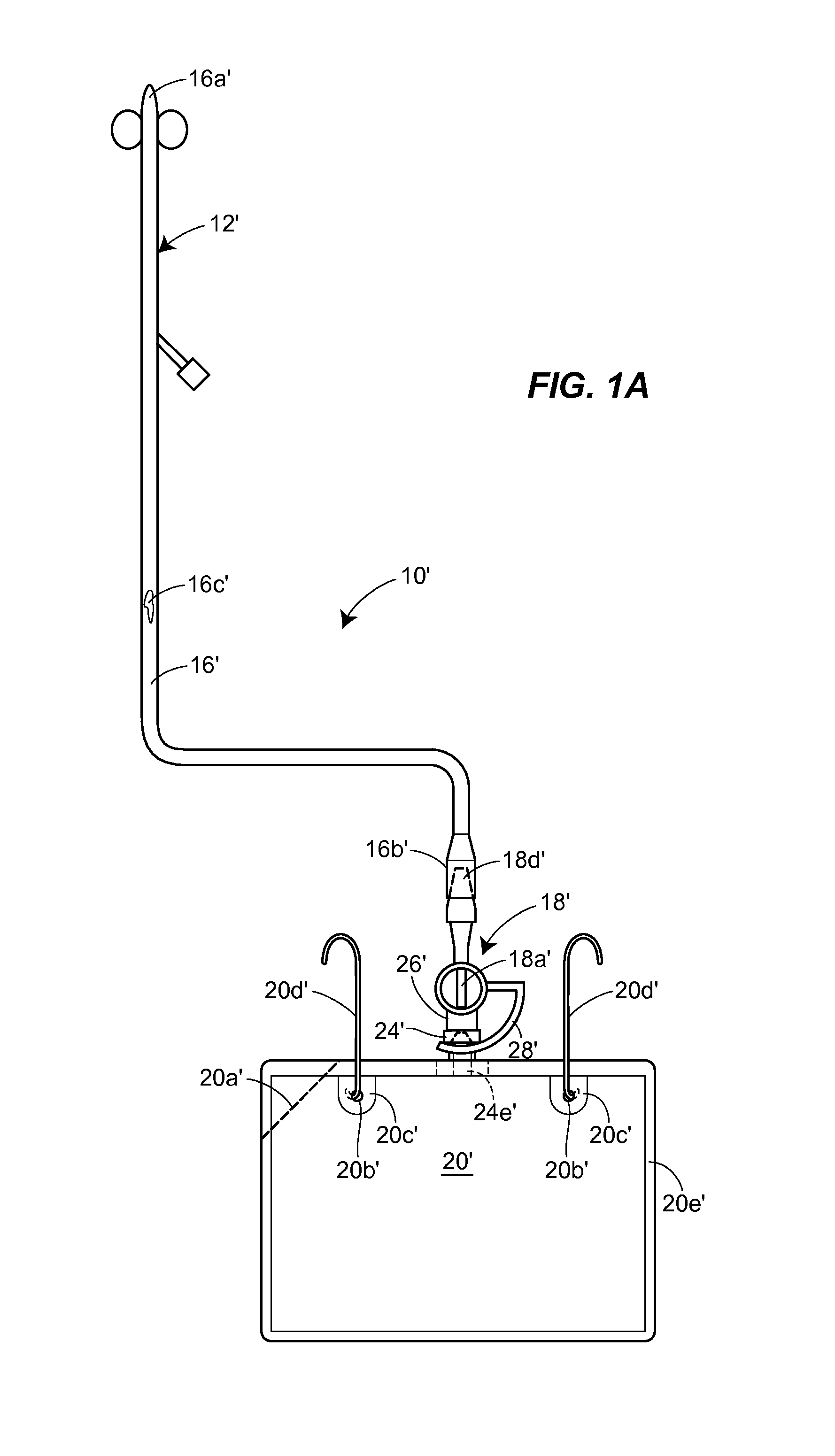
[0033]In an alternative embodiment illustrated in FIG. 1A, the tubing element 16′ of the Foley catheter collection system 10′ comprises the catheter tube of a specially configured Foley catheter 12′. It will be seen from FIG. 1A that the first end 16a′ of the tubing element 16′ comprises the insertion end of the specially configured Foley catheter ...


PUM


Abstract

A Foley catheter drainage collection system which is capable of permitting the removal and reconnection of drainage bags without compromising the sterility of the drainage system lumen. The collection system has a tubing element which includes a drainage valve associated with an end thereof remote from the insertion end of a Foley catheter. The drainage valve associated with the tubing element is movable from an open catheter drainage position to a closed position. The collection system also includes a drainage bag having a first connector element associated therewith and a second connector element is associated with the drainage valve. The second connector element is adapted for mating engagement with the first connector element. The collection system further includes a retaining element for maintaining the connector elements in mating engagement when the drainage valve is disposed in the open catheter drainage position.

Description

REFERENCE TO RELATED APPLICATIONS[0001]This is a continuation-in-part under 35 USC §120 of International Patent Application No. PCT / US2010 / 047841, filed Sep. 3, 2010, which claims the benefit of the filing date of U.S. Provisional Appl. No. 61 / 239,607, filed Sep. 3, 2009. The disclosures of International Patent Application No. PCT / US2010 / 047841 and U.S. Provisional Appl. No. 61 / 239,607 are incorporated herein by reference.FIELD OF THE DISCLOSURE[0002]The present disclosure is generally directed to a catheter and drainage collection system suitable for use in the drainage of urine from the bladder of a patient and, more particularly, to a Foley (indwelling) catheter collection system that reliably maintains the sterility of the collection system lumen.BACKGROUND OF THE DISCLOSURE[0003]Medical professionals are very aware that infections secondary to the use of Foley catheters represent a significant healthcare burden. Clinical research indicates that with current catheter drainage sy...

Claims


Application Information

Patent Timeline
Patent Type & Authority Applications(United States)
IPC IPC(8): A61F5/44
CPCA61F5/4405A61M39/26A61M25/0017
Inventor GILMAN, THOMAS H.
Owner HOLLISTER INCORPORAED
Learn More