Guidewire with anchor

a technology of guidewires and anchors, which is applied in the direction of guide wires, catheters, etc., can solve the problems of valve insufficiency or paravalvular leakage, large manipulation requirements, and difficulty in achieving, so as to facilitate the removal of guidewires, reduce stress, and reduce the effect of anchoring for

Inactive Publication Date: 2012-07-05
ROYAL BROMPTON & HAREFIELD NHS TRUST
View PDF4 Cites 20 Cited by
  • Summary
  • Abstract
  • Description
  • Claims
  • Application Information

AI Technical Summary

Benefits of technology

[0023]Optionally, the anchor is formed so as to exert a force radially on the walls of the body cavity, duct or vessel that increases as a function of a pulling force applied by a user in a longitudinal direction of the guidewire. This arrangement allows the gripping force to increase in proportion to the force applied by a user. Thus, at least for forces up to a given threshold, the anchoring force provided by the anchor can be such as to balance an applied force (so that the guidewire does not move longitudinally) while minimising stress in the body cavity, duct or vessel caused by the presence of the anchor. In other words, rather than arranging for the anchor always to exert a radial force that is sufficient to sustain the maximum pulling force that the anchor is able to balance (i.e. a pulling force equal to the threshold force), the anchor of the present invention provides a variable radial force, allowing smaller radial forces where only a relatively small anchoring force is required.
[0024]For applied longitudinal forces above the threshold, the anchor may be configured simply to collapse, which facilitates removal of the guidewire without the need for separate apparatus. Manufacturing costs may therefore be reduced and it may also be advantageous to reduce the complexity and / or number of different components that need to be inserted into the patient via the guidewire. Alternatively, a removal catheter may be used to assist with removal of the guidewire after use.

Problems solved by technology

During procedures such as valve replacement, a great deal of manipulation is required to locate the delivery system at the site of interest.
As the guidewire end is free, this can be difficult to achieve.
If the valve is incorrectly aligned, valve insufficiency or paravalvular leak may occur.
This stiffness increases the risk of damage to the patient, such as pulmonary artery puncture.
However, the possibility of a fatal haemothorax remains.

Method used


Image

  • Guidewire with anchor
  • Guidewire with anchor
  • Guidewire with anchor

Examples


Embodiment Construction

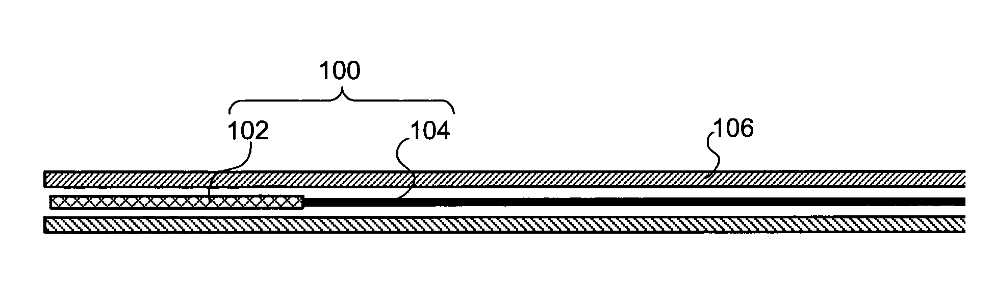
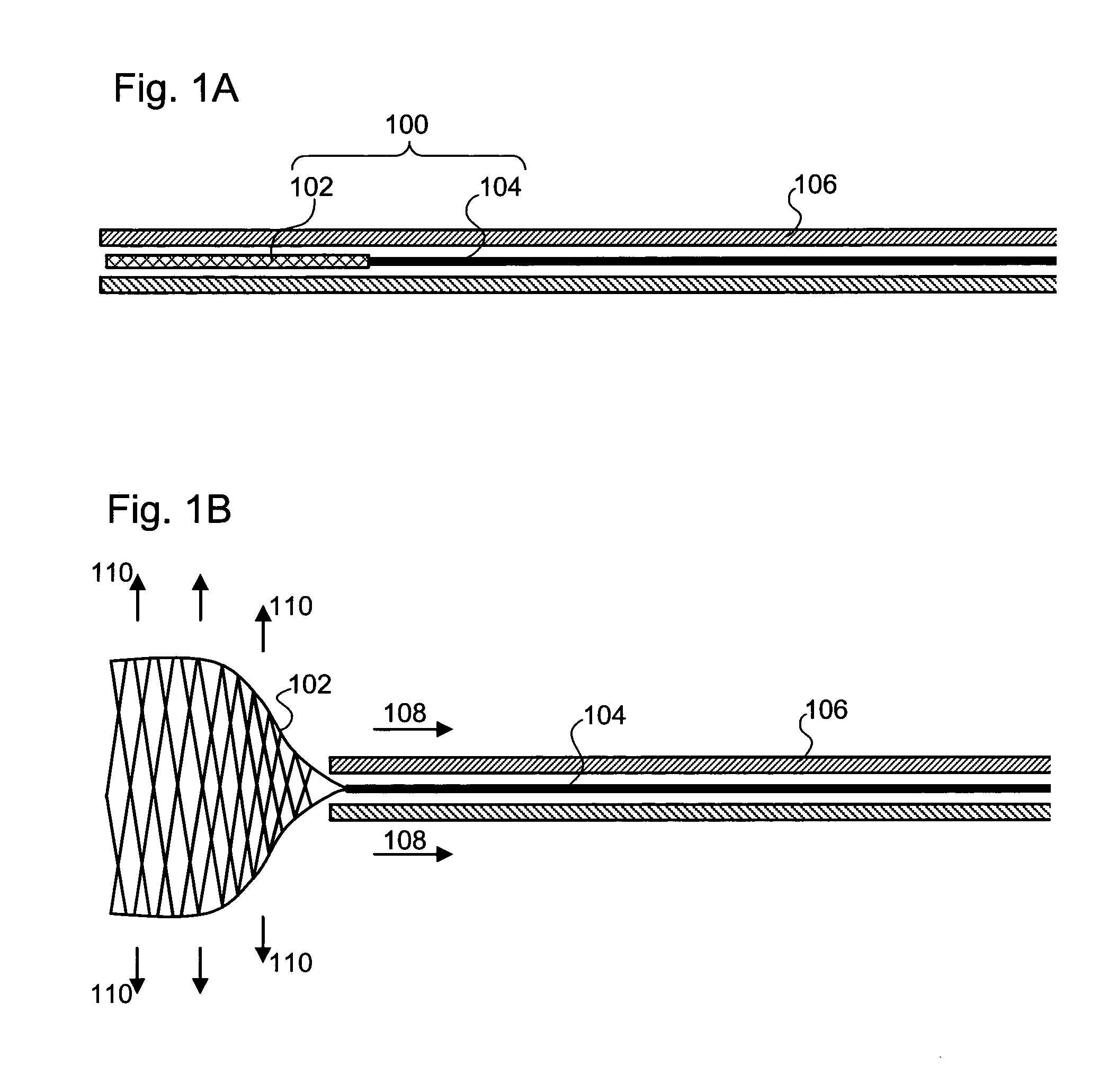
[0056]FIGS. 1A and 1B show an example of a guidewire 100 comprising a stem 104 and an anchor portion 102. In FIG. 1A, the guidewire is fully contained within a guidewire delivery catheter 106, which may be tubular in form, for example. The anchor 102 is radially constrained by the catheter 106, which may be desirable during an insertion phase to reduce the risk of injury or discomfort to a patient.

[0057]Once the guidewire is fully deployed within the body cavity, duct or vessel, the guidewire delivery catheter 106 can be longitudinally withdrawn (arrows 108) so as to expose the anchor 102. A guidewire 100 and catheter 106 in this configuration are shown in FIG. 1B. Being no longer radially constrained, the anchor 102 springs open (arrows 110) and can perform its function of anchoring the guidewire 100. The anchor 102 may be reversibly expandable, optionally through a plurality of cycles of expansion and retraction. This allows the anchor 102 to be removed easily and / or to be re-posi...


PUM


Abstract

A guidewire for a catheter, comprising: an anchor for providing an anchoring force that inhibits longitudinal movement of the guidewire when the guidewire is deployed within a body cavity, duct or vessel. The anchor can provide a gripping force by pressing outwards against the tissue and in such a way that a closed path contact line between the anchor and tissue is defined. A system for cardiovascular intervention using a guidewire with anchor. A deployment system for a guidewire with anchor.

Description

BACKGROUND OF THE INVENTION[0001]The present invention relates to a guidewire for a catheter, a deployment system for a guidewire and a method of using the guidewire and deployment system. In particular, the present invention relates to a guidewire having an anchoring mechanism for controlling and / or limiting longitudinal displacement of the guidewire when fully deployed.[0002]Guidewires are commonly used to facilitate access to cavities within the body such as the cardiovascular, gastrointestinal and urological systems. Guidewires provide a first route to the site of interest, and delivery systems can be passed over the wire to reach the site with a minimum level of trauma and without loss of position.[0003]Interventional cardiology guidewires are used within the vascular lumens of the patient to access the heart. Wires are generally introduced into the femoral artery or vein at the groin and fed up to the left or right side of the heart.[0004]For example, coronary guidewires may b...

Claims


Application Information

Patent Timeline
Patent Type & Authority Applications(United States)
IPC IPC(8): A61M25/09
CPCA61M2025/0096A61M25/09A61M25/04
Inventor MULLEN, MICHAEL
Owner ROYAL BROMPTON & HAREFIELD NHS TRUST
Why Eureka
Try Eureka