
Device for estimating turning characteristic of vehicle

a technology for estimating the turning characteristic and vehicles, applied in the direction of vehicle position/course/altitude control, process and machine control, instruments, etc., can solve the problems of preventing the enhancement of affecting the estimation accuracy of the stability factor, etc., and achieves the effect of shorter time and higher accuracy

Active Publication Date: 2012-07-05
TOYOTA JIDOSHA KK
View PDF6 Cites 19 Cited by
  • Summary
  • Abstract
  • Description
  • Claims
  • Application Information

AI Technical Summary

Benefits of technology

[0009]According to the above-mentioned configuration, a stability factor of the vehicle is estimated on the basis of the relationship between vehicle lateral acceleration removed of the components having frequency equal to or lower than a first predetermined value and yaw rate deviation index value removed of the components having frequency equal to or lower than a second predetermined value. Accordingly, a stability factor can be estimated on the basis of vehicle lateral acceleration and yaw rate deviation index value which are reduced in steady detection error such as those due to zero point offset, whereby a stability factor can be estimated with higher accuracy than ever before.
[0020]According to this configuration, even when the change degree of the estimated values of stability factor and time constant coefficient of steering response are high, a stability factor can be estimated with higher accuracy as compared with a case where a final adjusting gain is not determined on the basis of the first and the second adjusting gains.

Problems solved by technology

For that reason, in the conventional turning characteristic estimating devices such as that disclosed in the above-mentioned Laid-Open Publication, estimation of stability factor is liable to be affected by the detection error, which precludes enhancing estimation accuracy of stability factor.

Method used


Image

  • Device for estimating turning characteristic of vehicle
  • Device for estimating turning characteristic of vehicle
  • Device for estimating turning characteristic of vehicle

Examples


first embodiment

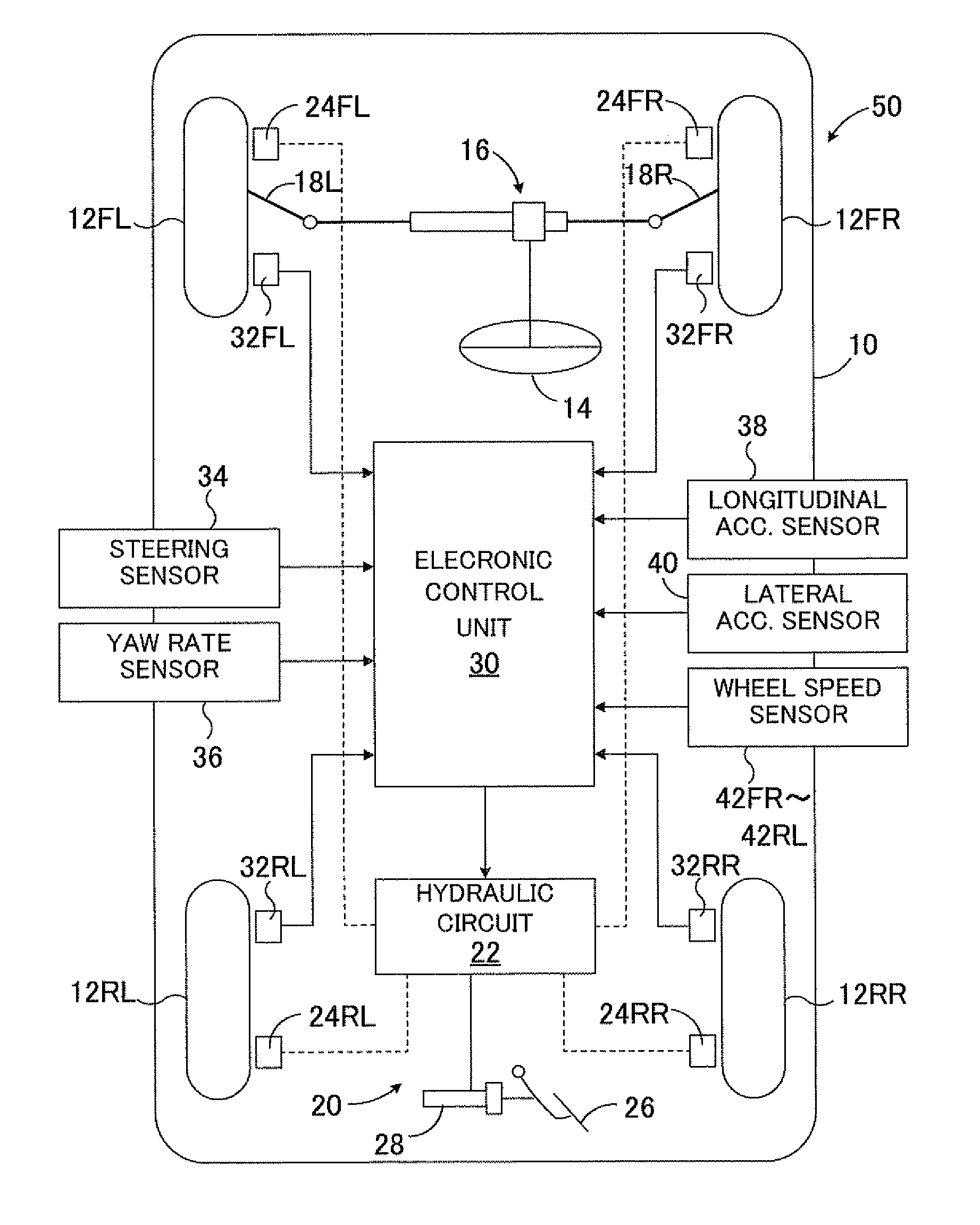
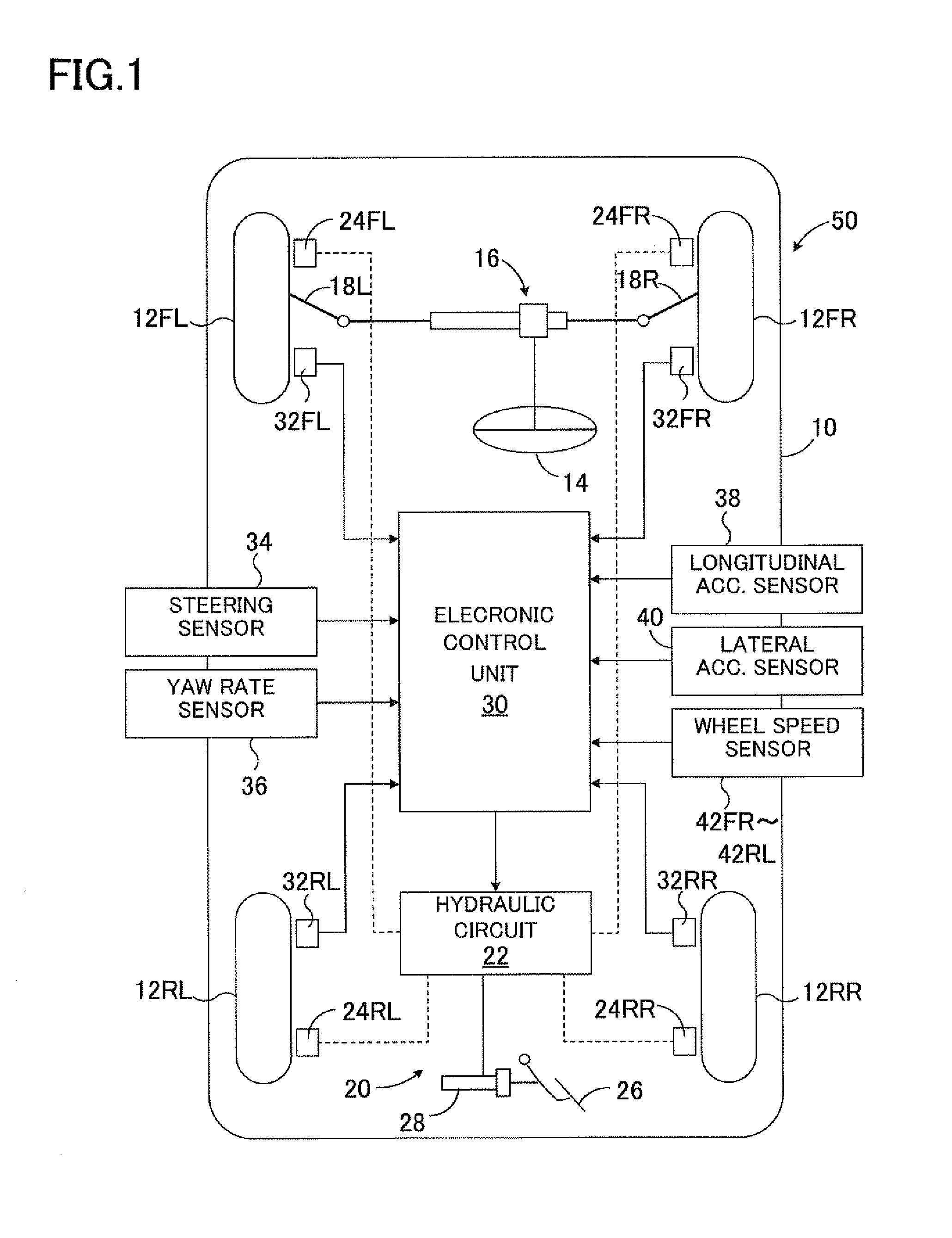
[0085]FIG. 1 is a schematic diagram showing a first embodiment of a turning characteristic estimation device according to the present invention, the device being applied to a vehicle motion control device.

[0086]In FIG. 1, 50 denotes an entire vehicle motion control device for a vehicle 10. The turning characteristic estimation device according to the present invention is a part of the vehicle motion control device 50. The vehicle 10 has a right front wheel 12FR, a left front wheel 12FL, a right rear wheel 12RR, and a left rear wheel 12RL. The right and left front wheels 12FR, 12FL, which are steerable wheels, are steered by an unillustrated steering apparatus of a rack and pinion type via right and left tie rods 18R and 18L, respectively. The steering apparatus is driven in response to steering operation of a steering wheel 14 by a driver.

[0087]Braking forces of the left and right front wheels 12FL, 12FR and the left and right rear wheels 12RL, 12RR are controlled through control of...

second embodiment

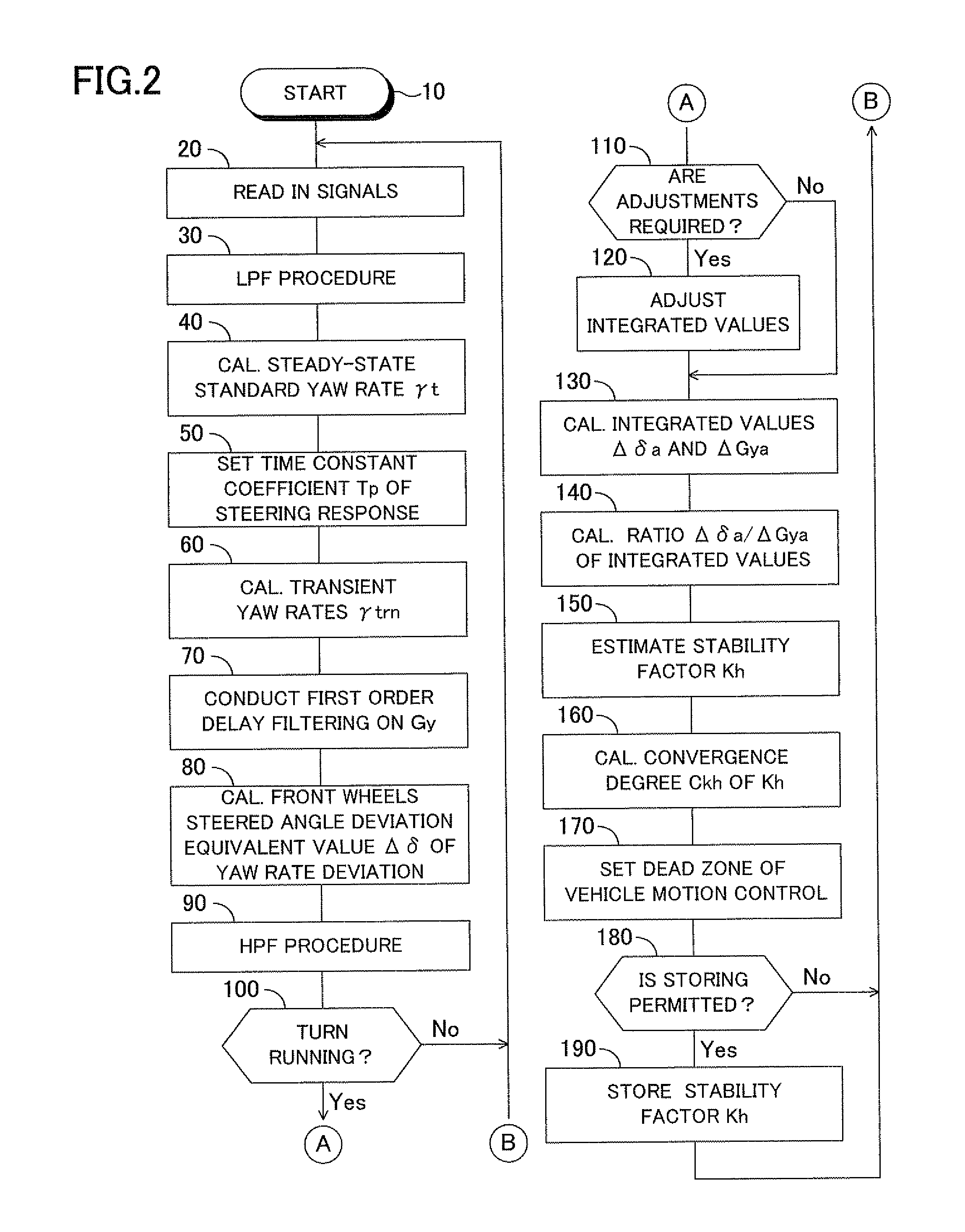
[0140]FIG. 4 is a flowchart showing a main portion of a routine for calculating a stability factor Kh by estimation in a second embodiment of the turning characteristic estimation device according to the present invention which is configured as a modification of the first embodiment. In FIG. 4, steps identical to those shown in FIG. 2 are denoted by the same step numbers. The same goes in the flowcharts for the embodiments described hereinafter.

[0141]In this second embodiment, after completion of step 80, the number of reciprocating steering operations by a driver per unit time is calculated as steering frequency fs in step 82. A cutoff frequency fhc of a high-pass filtering procedure in step 90 is also calculated on the basis of the steering frequency fs from a map corresponding to the graph shown in FIG. 5 so that as the steering frequency fs decreases, the cutoff frequency fhc lowers.

[0142]In the high-pass filtering procedure on the vehicle lateral acceleration Gyft and the front...

third embodiment

[0146]FIG. 5 is a flowchart showing a main portion of a routine for calculating a stability factor Kh by estimation in a third embodiment of the turning characteristic estimation device according to the present invention which is configured as a modification of the first embodiment.

[0147]In this third embodiment, after completion of step 80, the number of reciprocating steering operations by a driver per unit time is calculated as steering frequency fs in step 84. A cutoff frequency fhc of a high-pass filtering procedure is also calculated on the basis of the steering frequency fs and longitudinal acceleration Gx of the vehicle from a map corresponding to the graph shown in FIG. 7 so that as the steering frequency fs decreases, the cutoff frequency fhc lowers and as the absolute value of longitudinal acceleration Gx of the vehicle increases, the cutoff frequency fhc also increases.

[0148]In the high-pass filtering procedure on the vehicle lateral acceleration Gyft and the front wheel...


PUM


Abstract

A device for estimating turning characteristic of a vehicle estimates a stability factor indicating the turning characteristic of a vehicle. The device for estimating the turning characteristic calculates the transient yaw rate of a vehicle involved in the relationship of a primary delay relative to the steady-state standard yaw rate of a vehicle, and calculates the deviation between the transient yaw rate of the vehicle and the actual yaw rate of the vehicle. The device for estimating the turning characteristic corrects the estimated value of the stability factor so as to approach the true stability factor by correcting the initial value of the stability factor supplied to the calculation of the standard yaw rate of the vehicle on the basis of the relationship between the deviation of the yaw rate and the lateral acceleration of the vehicle so that the transient yaw rate of the vehicle approaches the true yaw rate.

Description

TECHNICAL FIELD[0001]The present invention relates to a device for estimating the turning characteristic of a vehicle and, more particularly, to a device for a vehicle which estimates a stability factor of the vehicle that represents the turning characteristic of a vehicle on the basis of a standard yaw rate of the vehicle and a transient yaw rate of the vehicle when the vehicle turns.BACKGROUND ART[0002]Assume that an actual yaw rate of a vehicle has a relationship of first order delay to a standard yaw rate of the vehicle and a coefficient multiplied to a vehicle speed in a time constant of the first order delay is referred to a time constant coefficient of steering response. A stability factor of the vehicle and a time constant coefficient of steering response t represent a turning characteristic of the vehicle. A stability factor of the vehicle and a steering-response-time constant coefficient can be estimated by using ARX (auto-regressive exogenous model) to estimate parameters...

Claims


Application Information

Patent Timeline
IPC IPC(8): G06F7/00B60W40/10
CPCB60W40/11B60W40/112B60W2520/14B60W2050/0088B60W2520/125B60W40/114B60W30/02B60W2050/0043B60W30/18145
Inventor YOKOTA, TAKAHIRO
Owner TOYOTA JIDOSHA KK
Learn More