Linking-Up Ventilation Door/Window Panel Structure

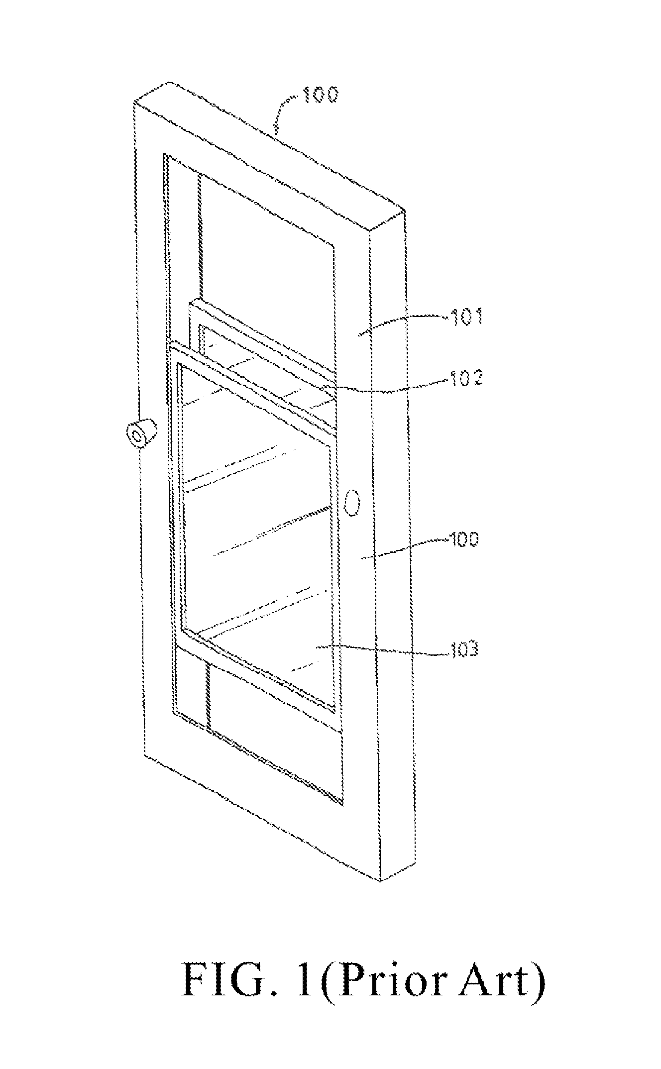
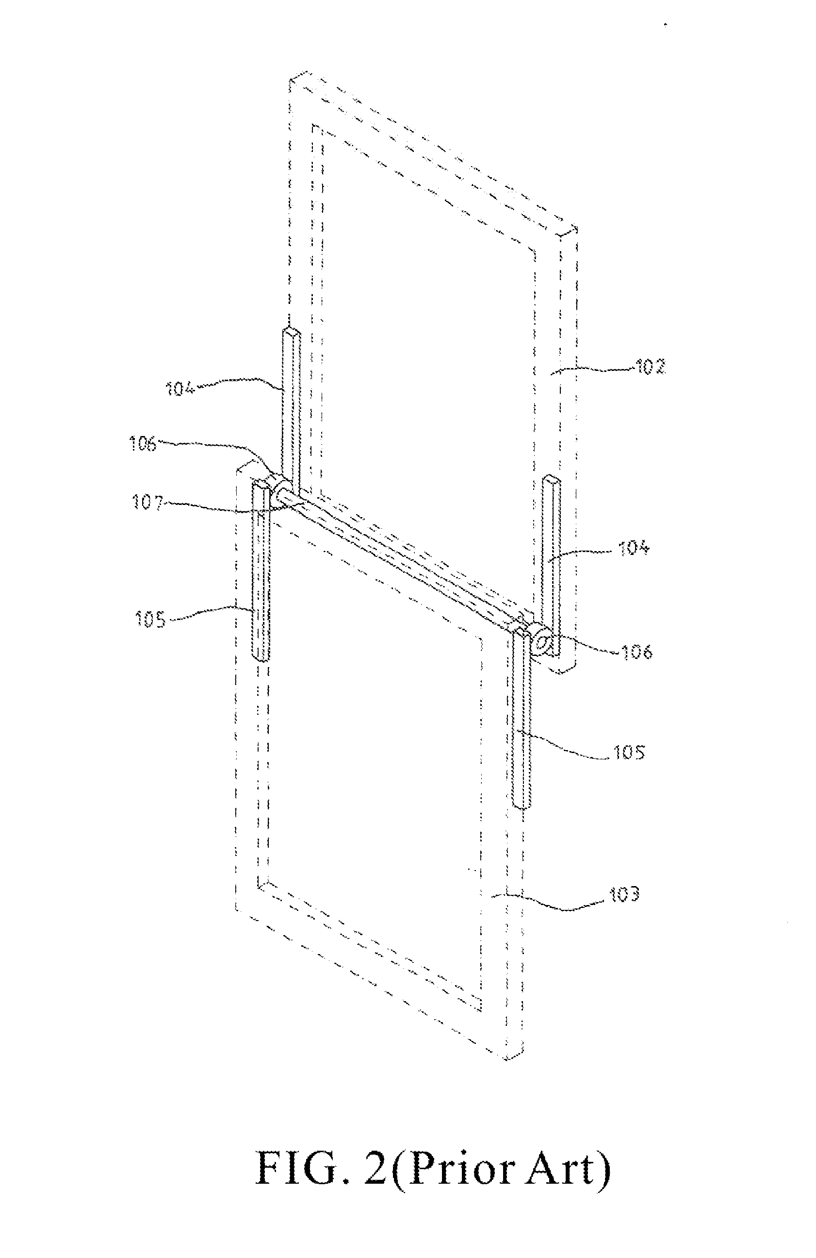
a ventilation door and window panel technology, applied in the direction of condensed water draining off, construction, building components, etc., can solve the problems of large load of the gear body 106, loud noise, damage of the gear body b>, etc., to facilitate operation stability and reduce noise

Inactive Publication Date: 2012-07-12
TAROKO DOOR & WINDOW TECH
View PDF13 Cites 0 Cited by
  • Summary
  • Abstract
  • Description
  • Claims
  • Application Information

AI Technical Summary

Benefits of technology

[0003]The first objective of the present invention provides a linking-up ventilation door / window panel structure. The linking-up ventilation door / window panel structure includes a window panel, at least one gear set, and a upper ventilation panel and a lower ventilation panel sliding on the window panel. The gear set is positioned between the upper ventilation panel and a lower ventilation panel. Each of the gear sets has a first gear rack and a second gear rack and two gears are positioned between the first gear rack and the second gear rack. The linking-up ventilation door / window panel structure having two gears facilitates the operation stability and reduces the noise formed by the linking-up ventilation door / window panel structure.

Problems solved by technology

However, the conventional linking-up ventilation panel structure only utilizes a gear body 106 for driving the panel structure.
In this case, the gear body 106 has a large loading and generates a loud noise.
Further, when the upper ventilation panel and the lower ventilation panel is installed with thicker (greater than 5 mm) glass therein, the loading of the glass exerts on the gear body 106 so that the gear body 106 are driven under extra loading, which result in the damage of the gear body 106.

Method used


Image

  • Linking-Up Ventilation Door/Window Panel Structure
  • Linking-Up Ventilation Door/Window Panel Structure
  • Linking-Up Ventilation Door/Window Panel Structure

Examples


first embodiment

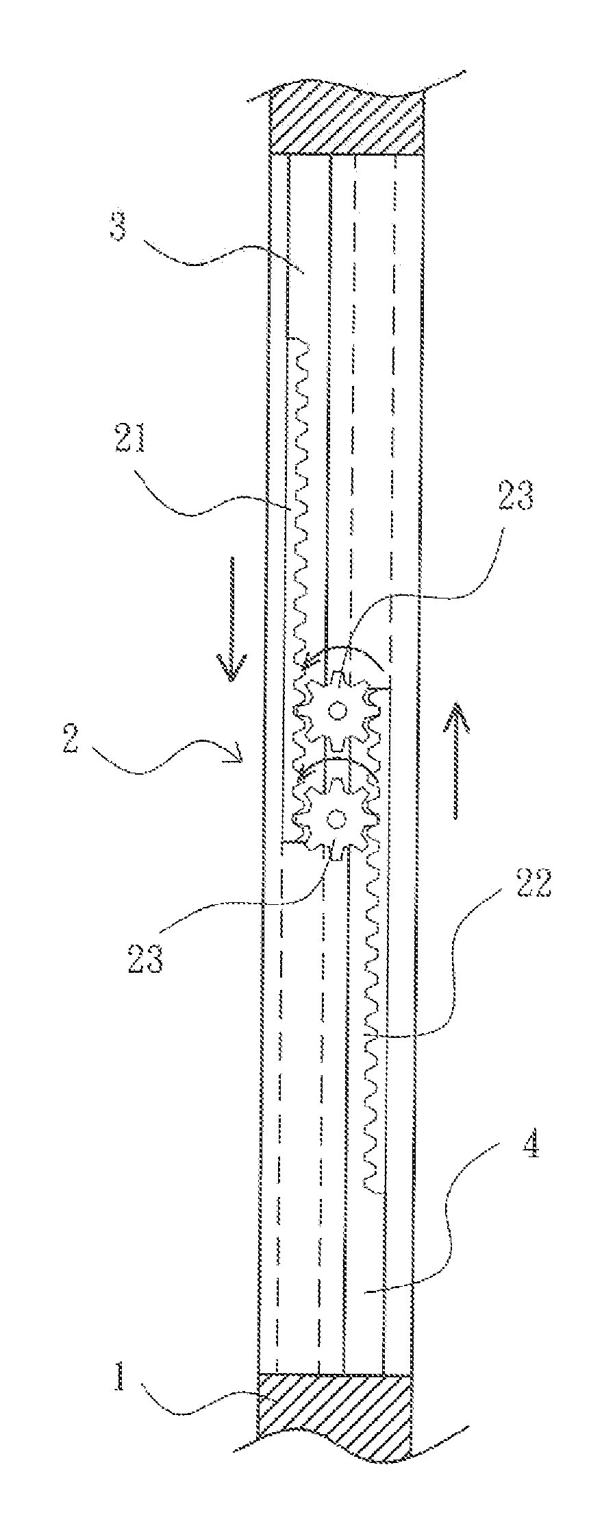
[0027]FIGS. 3A-3B are schematic lateral cross-sectional views of linking-up ventilation door / window panel structure according to the present invention. The linking-up ventilation door / window panel structure includes a window panel 1, at least one gear set 2, and a upper ventilation panel 3 and a lower ventilation panel 4 sliding on the window panel therein 1. The at least one gear set 2 has at least a first gear rack 21 and a second gear rack 22, The linking-up ventilation door / window panel structure is characterized in that two gears 23 are positioned between the first gear rack 21 and the second gear rack 22 of the gear set 2.

[0028]As shown in FIGS. 3A-3B, the first gear rack 21 and the second gear rack 22 are positioned in lateral sides respectively of the upper ventilation panel 3 and the lower ventilation panel 4, the two gears 23 are engaged between the first gear rack 21 and the second gear rack 22, and the two gears 23 are pivotally connected to the window panel 1 and / or pos...

second embodiment

[0036]In the present invention, the linking-up ventilation door / window panel structure utilizes the height difference between the first gear rack 21 and the second gear rack 22 and the width difference between the first gear 23a and the second gear 23b for driving the gear set 2′. The driving sequence of the gear set 2′ is that the first gear rack 21, the first gear 23a, the second gear 23b and the second gear rack 22, but not limited.

[0037]Please refer to FIGS. 6 and 7. FIG. 6 is schematic partial front cross-sectional view of linking-up ventilation door / window panel structure according to a third embodiment of the present invention. FIG. 7 is schematic partial top view of linking-up ventilation door / window panel structure according to the third embodiment of the present invention. The third embodiment is similar to the second embodiment but the difference is that the gear set 2″ has a first gear rack 21 and the second gear rack 22 wherein the heights of the first gear rack 21 and ...


PUM


Abstract

A linking-up ventilation door/window panel structure is described. The linking-up ventilation door/window panel structure includes a window panel, at least one gear set, and a upper ventilation panel and a lower ventilation panel sliding on the window panel, wherein the at least one gear set has at least a first gear rack and second gear rack. A first gear and a second gear are positioned between the first gear rack and the second gear rack and the two gears are pivotally connected to the window panels or the upper ventilation panel and the lower ventilation panel. The linking-up ventilation door/window panel structure links up the other ventilation panel for ventilating air when the user shifts one of the upper ventilation panel and the lower ventilation panel. The linking-up ventilation door/window panel structure having two gears facilitates the operation stability and reduces the noise formed by the linking-up ventilation door/window panel.

Description

FIELD OF THE INVENTION[0001]The present invention relates to a linking-up ventilation door / window panel structure, and more particularly to a linking-up ventilation door / window panel structure having two gears for facilitating operation stability and reducing the noise formed by the linking-up ventilation door / window panel structure.BACKGROUND OF THE INVENTION[0002]Within the indoor space of the building, ventilation window is positioned in the door or the window besides the wall has windows for ventilation. As shown in FIGS. 1 and 2, Taiwan Issued Patent Number 282,815 discloses a conventional linking-up ventilation panel structure, characterized in that a upper air door 102 and a lower air door 103 are positioned in the frame 101 of the door body 100. The upper air door 102 and the lower air door 103 can be adjusted along the frame 101 by the user for upward and downward movement. The gear racks 104 are positioned in the bottom sides of the upper air door 102 and the gear racks 10...

Claims


Application Information

Patent Timeline
Patent Type & Authority Applications(United States)
IPC IPC(8): E06B3/44
CPCE06B3/72E06B3/44
Inventor HUANG, KUN-ZHIHUANG, QIU-HUI
Owner TAROKO DOOR & WINDOW TECH
Why Eureka
Try Eureka