Lightweight armor and ballistic projectile defense apparatus

a technology of ballistic projectiles and armor, applied in the field of armor materials and equipment, can solve the problems of reducing the penetration ability of soft vests, reducing the protection ability of wearers, and difficulty in providing easily retrofittable and/or transportable armor materials

Active Publication Date: 2012-07-12
SUPRACOR
View PDF13 Cites 32 Cited by
  • Summary
  • Abstract
  • Description
  • Claims
  • Application Information

AI Technical Summary

Benefits of technology

[0023]An important advantage of the present invention is that it provides an extremely lightweight armor structure that can be formed to mate with any contour of an object or body to be protected.
[0024]Another advantage of the present invention is that it provides a lightweight armor structure that can be formed to at least partially envelope parts of a wearer body to be protected.
[0025]Still another advantage of the present invention is that it provides a lightweight armor structure having means to permit warming or cooling fluid flow therethrough.
[0026]Yet another advantage of the present invention is that it provides a multilayered assembly having a hardened outer component that can be used to make armor in planar as well as shaped or contoured form.
[0027]A still further advantage of the present invention is that it provides an assembly that can be used to provide armor for vehicles, shelters or personnel.
[0028]An additional advantage of the present invention is that it can be configured to provide threat protection meeting various governmental standards.

Problems solved by technology

While means for opposing a particular type of ballistic threat can usually be designed and / or configured for inclusion in original equipment, the provision of easily retro-fittable and / or transportable armor materials is more difficult in that it must usually have characteristics such as formability, relative lightness in weight, durability in hostile environments, and other particular attributes such as having the capability of deflecting or capturing incoming projectiles.
Soft vests per se do not protect the wearer by deflecting bullets.
This tends to deform the bullet, further reducing its ability to penetrate.
However, while a vest can prevent invasive bullet wounds, the wearer's body must still absorb the bullet's energy, and can often incur blunt force trauma in which a majority of users experience only bruising; but impacts can still cause severe internal injuries.
Another problem with soft vests is that they offer little protection against arrows, ice picks, stabbing knife blows, bullets with their points sharpened, and armor-piercing rounds because the striking force is concentrated in a relatively small area and can often push or be pushed through the weave of bullet-resistant fabrics.
Also, since soft body armor vests are usually ineffective against most military rifle rounds, some such vests may be augmented with metal, ceramic or polyethylene plates that are carried in pockets included in the vest to provide extra protection to vital areas.
However, these plated vests still have shortcomings because the energy of large fragments or high velocity bullets hitting some types of plates can still cause life-threatening, blunt trauma injuries.
Unfortunately, because of the weight, such vests are often discarded and the soldier is left unprotected.
In addition, since the plates often merely deflect the projectile or its resulting spall, it is not unusual for a wearer to survive the initial impact only to receive substantial and even lift threatening injury as the deflected material strikes another part of his body.
For example, many plated vest wearers have received devastating injury to their face, arms or head as a result of bullet spall deflected from the surface of a vest carried hard armor plate.
Unfortunately, this increases the overall weight and thickness of the garment and reduces its flexibility.
Although Kevlar has long been used, some of the newer materials are said to be lighter, thinner and more resistant than Kevlar, but are considerably more expensive.

Method used


Image

  • Lightweight armor and ballistic projectile defense apparatus
  • Lightweight armor and ballistic projectile defense apparatus
  • Lightweight armor and ballistic projectile defense apparatus

Examples


Embodiment Construction

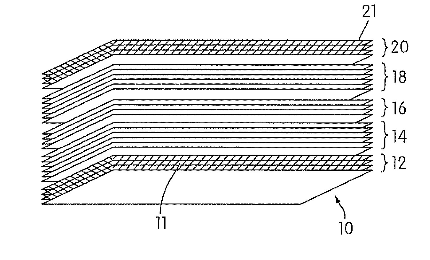
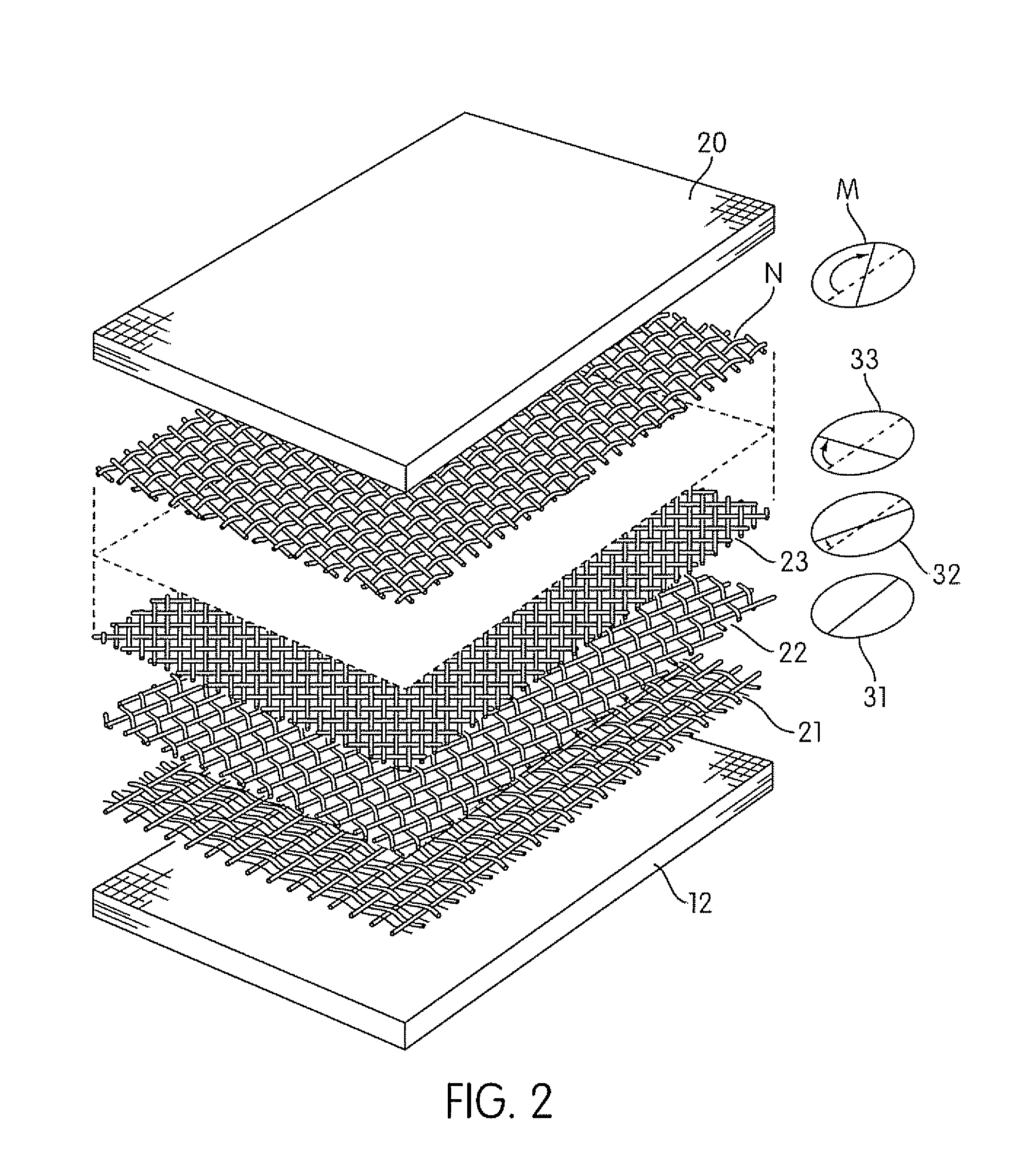
[0044]Referring now to FIG. 1 of the drawing, an illustration is provided showing at 10 a stack of fabric layers of high strength woven or non-woven sheet material including five subsets of layers 12-20 in accordance with one embodiment of the present invention. As depicted, the first subset 12 includes 4 plys of woven carbon fiber cloth; the second subset 14 includes 6 plys of Kevlar 29® woven fabric made by E. I. du Pont de Nemours and Company; the third subset 16 includes 4 plys of carbon fiber cloth of the same type used in subset 12; the fourth subset 18 includes 6 plys of Kevlar 29® woven fabric of the same type used in subset 14; and the subset 20 includes 4 plys of carbon fiber cloth of the same type used in subset 12. As suggested by the hatching at 11 and 21, the carbon cloth layers of subsets 12 and 20 (and possibly subset 16) are impregnated with an epoxy resin so that when compressed and cured the form rigid front and back shells for the armor component. The layers form...


PUM

PropertyMeasurementUnit
yield strengthsaaaaaaaaaa
thicknessaaaaaaaaaa
thicknessaaaaaaaaaa

Abstract

Ballistic resistant armor material and assembly including a thin, rigid armor component for stopping and capturing ballistic projectiles, backed by a resilient component formed of thermoplastic elastomeric honeycomb material for absorbing projectile strike energy and reducing impact noise and / or blunt trauma injury. The armor component includes multiple layers of high tensile strength aramid fabric or the like sandwiched between front and back plates made of multiple layers of woven carbon cloth impregnated with an epoxy resin or the like. The several layers of the armor component are formed and compressed to provide a rigid outer shell that can advantageously be configured as planar or shaped to suit particular applications. The resilient component is affixed to the inside surface of the armor component and may include one or more layers of flexible honeycomb material having cells that are open, hermetically sealed, or perforated to provide fluid circulation therethrough.

Description

FIELD OF THE INVENTION[0001]The present invention generally relates to armor materials and apparatus for resisting the ballistic forces of bullets and other projectiles, and more particularly, to an armor assembly and apparatus formed of layered formable materials configurable to provide a defensive covering or shield for protection of personnel, shelters and vehicles.BACKGROUND OF THE INVENTION[0002]In law enforcement and military environments it is often necessary and appropriate to use protective shields of various forms and configurations to protect personnel and equipment from injury or mechanical damage caused by projectiles including bullets, spall, shrapnel, etc. The shielding apparatus may be of a type that is worn as protective personnel body armor; a type that is used to provide protective panels for a land, sea or air vehicle; a type that may be configured to provide a shelter; or merely a collection of panels that can be affixed to a wall of a shelter to prevent penetra...

Claims


Application Information

Patent Timeline
Patent Type & Authority Applications(United States)
IPC IPC(8): F41H5/04F41H1/02
CPCF41H1/02F41H5/08F41H5/0478F41H5/0471
Inventor LANDI, CURTIS L.
Owner SUPRACOR
Why Eureka
Try Eureka