Controller of Valve Timing Control Apparatus and Valve Timing Control Apparatus of Internal Combustion Engine

a control apparatus and valve timing technology, applied in the direction of valve arrangements, machines/engines, non-mechanical valves, etc., can solve the problem of unstable control state of the phase control system

Active Publication Date: 2012-07-12
HITACHI ASTEMO LTD
View PDF5 Cites 24 Cited by
  • Summary
  • Abstract
  • Description
  • Claims
  • Application Information

AI Technical Summary

Benefits of technology

[0004]It is, therefore, in view of the previously-described disadvantages of the prior art, an object of the invention to provide a controller of a valve timing control apparatus and a valve timing control appa

Problems solved by technology

However, the valve timing control device disclosed in JP2010-138735, suffers from the drawback that, when initiating relative-phase control between the crankshaft and the camshaft during an engine starting period, in particular, when starting with a cold engine, an electric motor is driven from its stopped state and thus a time

Method used


Image

  • Controller of Valve Timing Control Apparatus and Valve Timing Control Apparatus of Internal Combustion Engine
  • Controller of Valve Timing Control Apparatus and Valve Timing Control Apparatus of Internal Combustion Engine
  • Controller of Valve Timing Control Apparatus and Valve Timing Control Apparatus of Internal Combustion Engine

Examples


Embodiment Construction

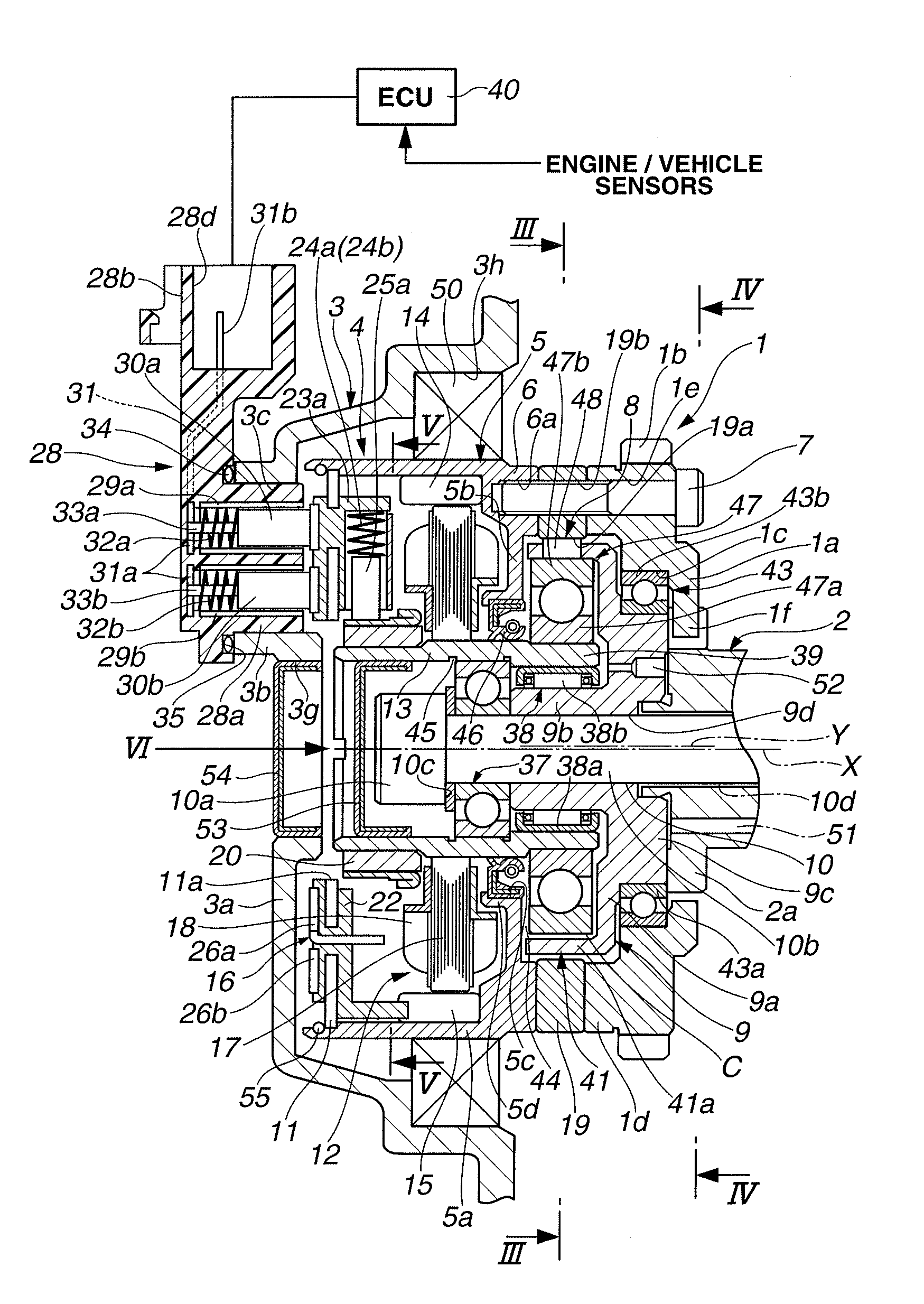
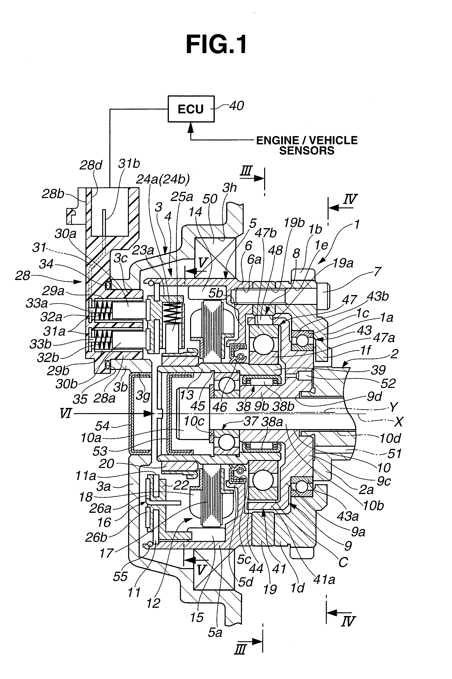
[0028]A valve timing control (VTC) apparatus of an internal combustion engine of the embodiment and its controller are hereinafter described in detail in reference to the drawings. In the shown embodiment, the VTC apparatus is applied to a valve operating system of the intake-valve side of the internal combustion engine. In lieu thereof, the VTC apparatus may be applied to a valve operating system of the exhaust-valve side of the engine

[0029]As shown in FIGS. 1-3, the VTC apparatus of the embodiment is comprised of a timing sprocket 1 (a drive rotary member) that rotates in synchronism with rotation of an engine crankshaft, a camshaft 2 rotatably supported on a cylinder head (an engine body not shown) through camshaft-journal bearings (not shown) and driven by torque transmitted from timing sprocket 1, a cover member 3 (a stationary member) laid out in front of the timing sprocket 1 and bolted to a chain cover (not shown), and a phase converter 4 installed between timing sprocket 1 ...


PUM


Abstract

In a valve timing control apparatus configured to execute phase-control via a phase converter, a controller is configured to control a phase angle of a camshaft relative to a crankshaft during an engine stopping period to a target phase angle differing from a required phase angle suited for an engine operating condition. The controller is further configured to change the phase angle of the camshaft toward the required phase angle during a time period from a point of time when cranking starts to a point of time when detection of a rotational position of the camshaft initiates during an engine restarting period. The controller is still further configured to start feedback-control for the phase angle of the camshaft from the point of time of initiation of detection of the rotational position of the camshaft for bringing the phase angle of the camshaft closer to the required phase angle.

Description

TECHNICAL FIELD[0001]The present invention relates to a controller of a valve timing control apparatus configured to variably control valve open timing and valve closure timing of each of engine valves, such as intake and / or exhaust valves, by the use of an electric motor, and specifically to an electric-motor-driven valve timing control apparatus of an internal combustion engine.BACKGROUND ART[0002]In recent years, there have been proposed and developed various electric-motor-driven valve timing control devices in which rotary motion (a torque) of an electric motor is transmitted via a speed reducer to a camshaft so as to change a relative angular phase between the engine crankshaft and the camshaft with the high control responsiveness and high controllability. One such electric-motor-driven valve timing control device has been disclosed in Japanese Patent Provisional Publication No. 2010-138735 (hereinafter is referred to as “JP2010-138735”). In the valve timing control device dis...

Claims


Application Information

Patent Timeline
IPC IPC(8): F01L1/344F01L9/22F01L9/40
CPCF01L2001/3521F01L1/352
Inventor KOKUBO, NAOKIKAWADA, SHINICHI
Owner HITACHI ASTEMO LTD
Why Eureka
Try Eureka