Contact tray and method employing same

a contact tray and tray technology, applied in the field of chemical processing columns, can solve the problems of improper installation of contact trays, significant impact on the efficiency of vapor-liquid or liquid-liquid interactions, and inability to meet the needs of the customer,

Active Publication Date: 2012-07-12
KOCH GLITSCH INC
View PDF1 Cites 22 Cited by
  • Summary
  • Abstract
  • Description
  • Claims
  • Application Information

AI Technical Summary

Benefits of technology

[0010]Each contact tray includes dividing walls that extend upwardly from the tray deck and are positioned between the cans and the downcomer inlets in the tray deck. The dividing walls are arranged on the tray deck in a manner to form groupings of one or more cans and one or more downcomer inlets, with the one or more cans within each grouping being in liquid-flow communication with the one or more downcomer inlets within that grouping. The dividing walls also isolate each grouping of one or more cans and one or more downcomer inlets from the cans and downcomer inlets in the other groupings to prevent liquid-flow communication between the groupings. The dividing walls thus force all, or substantially all, of the liquid stream exiting from the one or more cans in each grouping to flow only into the one or more downcomer inlets within that same grouping. In this manner, the dividing walls prevent the maldistribution and channeling of the liquid stream that would otherwise result if the contact tray should be installed or subsequently become positioned in a non-horizontal orientation, such as a result of a column upset or by wind load or wave action on the column.

Problems solved by technology

In mass transfer and heat exchange columns, the efficiency of the vapor-liquid or liquid-liquid interaction suffers significantly if the fluid streams are not uniformly distributed across the internal cross section of the column.
As a result of this channeling, the desired intermixing of the liquid and vapor streams is not achieved and the efficiency of the interaction suffers.
This problem can result from improper installation of the contact trays, when land-based columns sway under heavy wind loads, or when offshore columns are positioned on floating platforms, barges or ships and are subject to a rocking motion as a result of wind and wave action.

Method used


Image

  • Contact tray and method employing same
  • Contact tray and method employing same
  • Contact tray and method employing same

Examples


Embodiment Construction

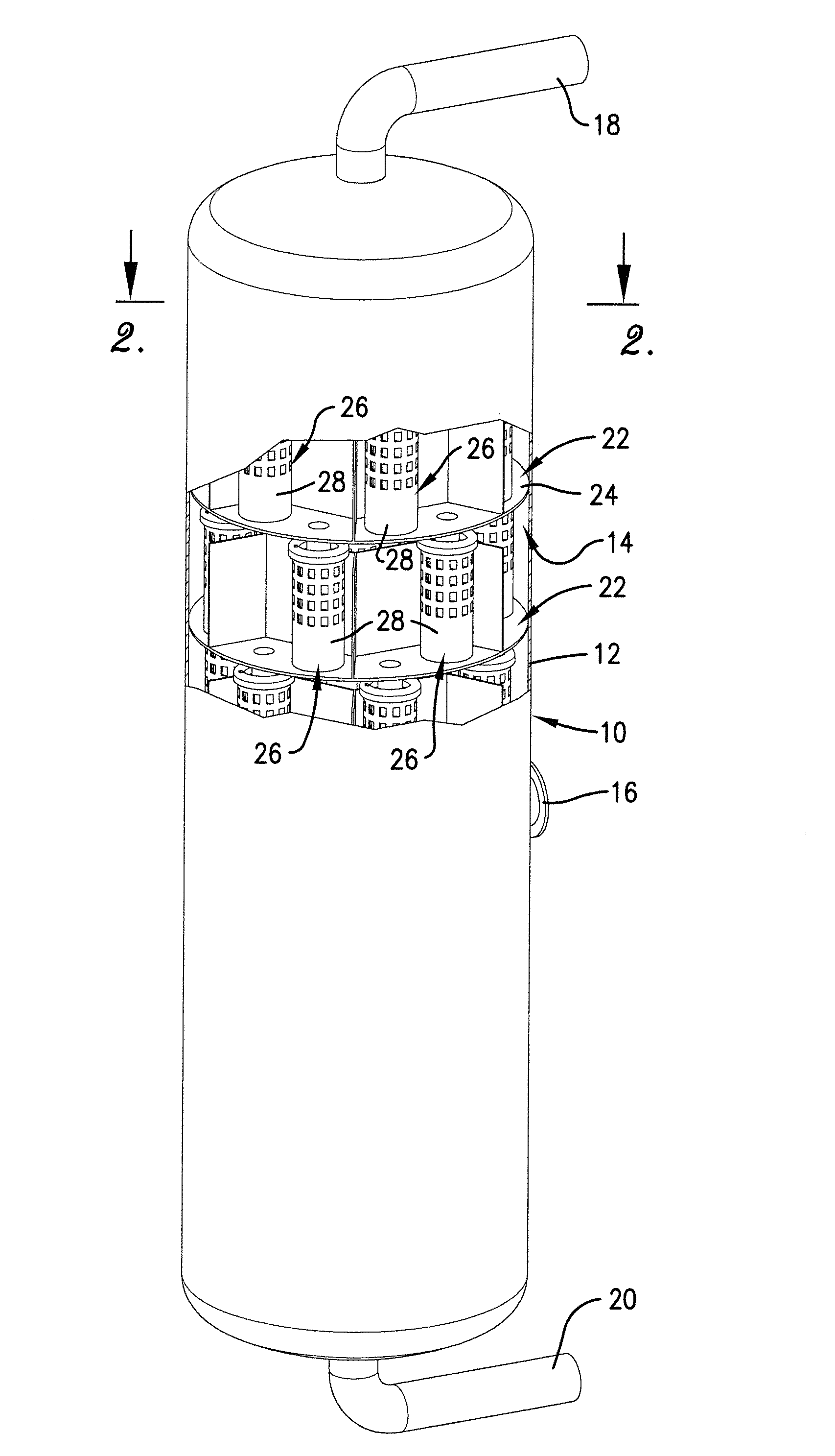
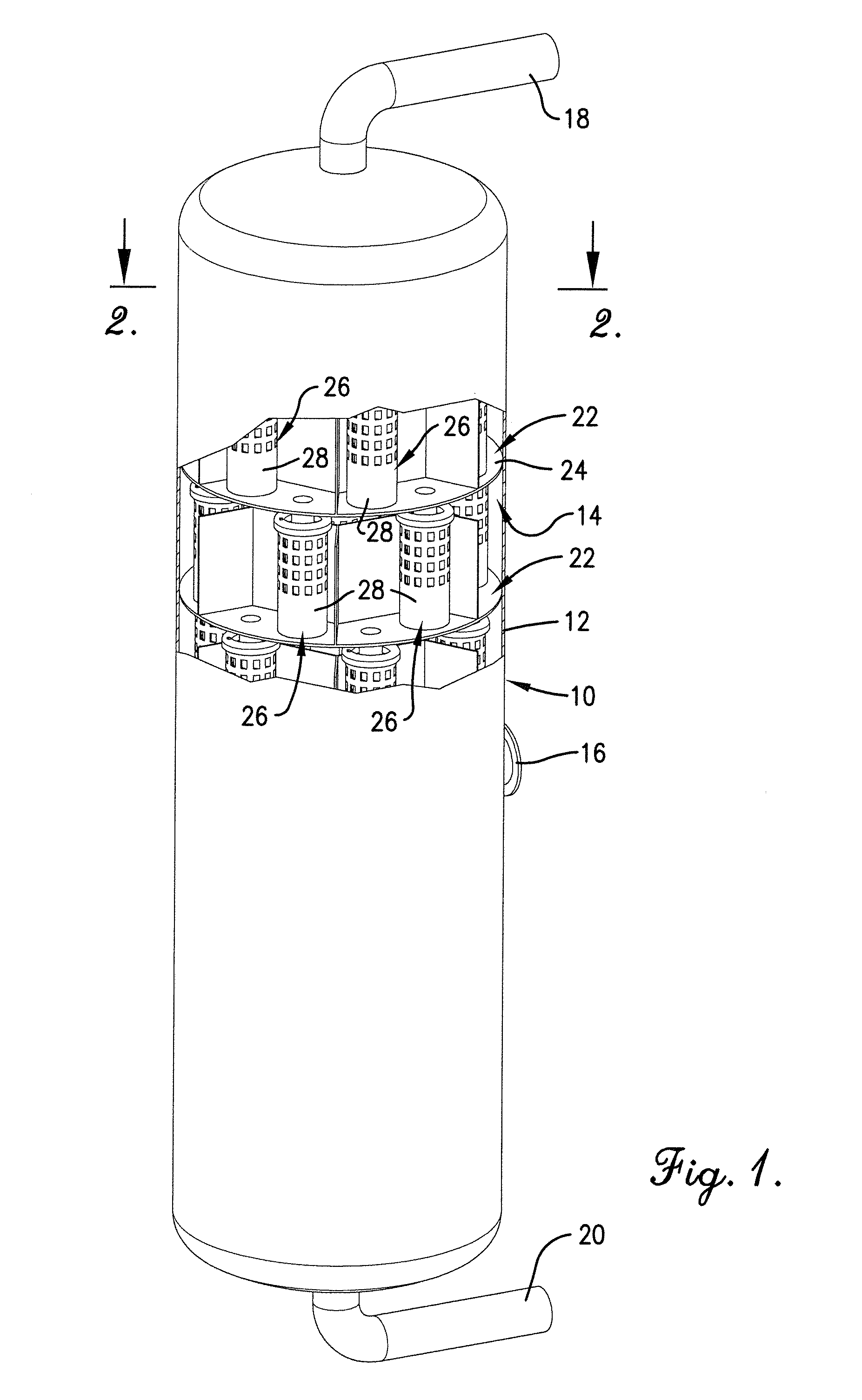
[0022]Turning now to the drawings in greater detail and initially to FIG. 1, a column suitable for use in processes in which mass transfer and / or heat exchange is intended to occur between countercurrent-flowing fluid streams is represented generally by the numeral 10. Column 10 includes an upright, external shell 12 that is generally cylindrical in configuration, although other configurations, including polygonal, are possible and are within the scope of the present invention. Shell 12 is of any suitable diameter and height and is constructed from one or more rigid materials that are desirably inert to, or are otherwise compatible with the fluids and conditions present during operation of the column 10.

[0023]Column 10 is of a type used for processing fluid streams, typically liquid and vapor streams, to obtain fractionation products and / or to otherwise cause mass transfer and / or heat exchange between the fluid streams. For example, column 10 can be one in which crude atmospheric, l...


PUM

PropertyMeasurementUnit
mass transferaaaaaaaaaa
heightaaaaaaaaaa
areasaaaaaaaaaa

Abstract

A contact tray is provided with a tray deck and dividing walls which form groupings of one or more cans and one or more downcomer inlets distributed across the tray deck. The cans have walls that surround vapor openings in the tray deck that permit upward passage of a vapor stream into the cans. Downcomers extend downwardly from the downcomer inlet and are positioned for delivering a liquid stream into the center of cans positioned on a tray deck of an underlying contact tray. Discharge openings are provided in the walls of the cans to allow the liquid stream to exit the cans. The dividing walls direct the exiting liquid stream into the downcomer inlets in the same grouping and prevent or impede the liquid stream from flowing to a low side of the tray deck.

Description

BACKGROUND OF THE INVENTION[0001]The present invention relates generally to chemical processing columns in which mass transfer and / or heat exchange between fluid streams occurs and, more particularly, to contact trays used in such columns to facilitate contact between fluid streams flowing within the column and methods of contacting the fluid streams using the contract trays.[0002]Contact trays are used within mass transfer and heat exchange columns to facilitate contact between fluid streams flowing in countercurrent relationship within the column. The fluid streams are typically an ascending vapor stream and a descending liquid stream, in which case the contact trays are commonly referred to as vapor-liquid contact trays. In some applications, both fluid streams are liquid streams and the contact trays are commonly referred to as liquid-liquid contact trays. In still other applications, the ascending fluid stream is a gas stream and the descending fluid steam is a liquid stream, i...

Claims


Application Information

Patent Timeline
Patent Type & Authority Applications(United States)
IPC IPC(8): B01F3/04
CPCB01D3/205B01D3/008B01D3/26B01D3/32B01D3/00F28C3/06F28C3/00
Inventor NIEUWOUDT, IZAK
Owner KOCH GLITSCH INC
Why Eureka
Try Eureka