Robot hand

a robot hand and hand technology, applied in the field of robot hands, can solve the problems of limited space for placing the robot hand to pick up the components, difficult to apply the robot hand to work for gripping a small object, and complicated structure and control of the robot hand

Active Publication Date: 2012-07-12
SEIKO EPSON CORP
View PDF13 Cites 23 Cited by
  • Summary
  • Abstract
  • Description
  • Claims
  • Application Information

AI Technical Summary

Benefits of technology

[0014]The robot hand according to the aspect adopts the system for translating the bases of finger members to grip an object. Therefore, the robot hand can grip a small object in a narrow work space while keeping an advantage that angles of the finger members in contact with an object do not change according to the size of the object. Therefore, such a robot hand can be suitably mounted on a robot that performs work for gripping a small object in a narrow work space.

Problems solved by technology

Therefore, the structure and the control of the robot hand are complicated.
However, in the robot hand adopting the system for translating the bases of the finger members, it is difficult to apply the robot hand to work for gripping a small object.
Usually, a space for placing the robot hand to pick up the components is limited.
Further, when the picked-up components are attached, since the components are small, the components often have to be assembled in a narrow space.
This makes it difficult to apply the robot hand to work in a narrow work space.

Method used


Image

  • Robot hand
  • Robot hand
  • Robot hand

Examples


Embodiment Construction

[0022]An embodiment is explained below according to the following order in order to clarify contents of the invention.

[0023]A. Structure of a robot hand according to this embodiment

[0024]B. Operation of the robot hand according to this embodiment C. Modification

A. Configuration of the Robot Hand According to this Embodiment

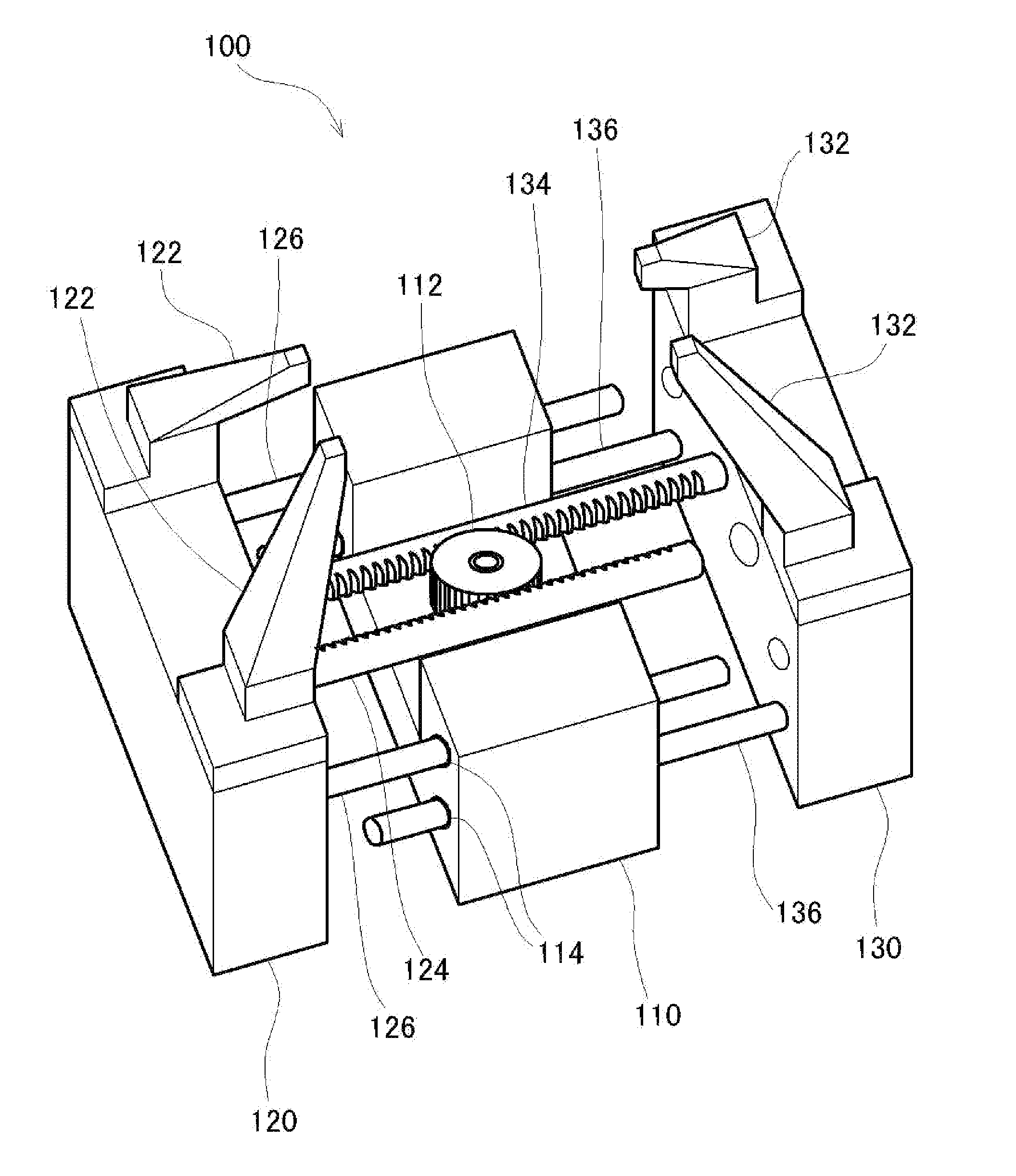
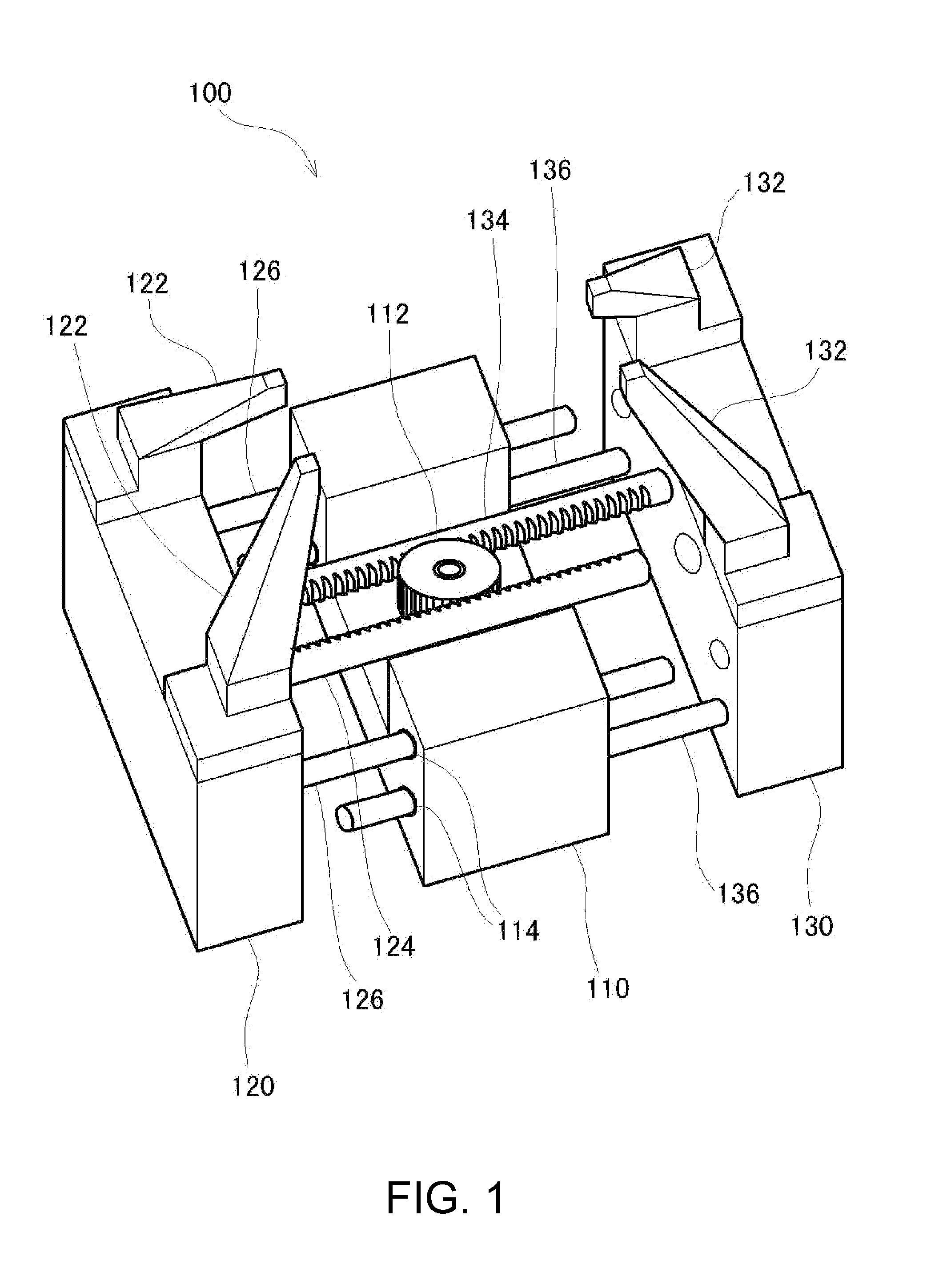
[0025]FIG. 1 is an explanatory diagram showing the structure of a robot hand 100 according to this embodiment. As shown in the figure, the robot hand 100 according to this embodiment roughly includes three sections. The section in the center includes a palm member 110 formed in a sectional shape in which a large groove is formed in the center of the upper side of a rectangular shape, a pinion gear 112 provided substantially in the center of the groove of the palm member 110, and a not-shown motor for rotating the pinion gear 112. Moving members 120 and 130 having a substantially rectangular parallelepiped shape are provided on the left and right of the palm member...


PUM


Abstract

A robot hand that changes a space between finger members provided apart from each other includes: moving members on which the finger members are vertically provided; a palm member including a moving mechanism for moving the moving members in a predetermined axial direction; and guide members that guide the movement of the moving members in the predetermined axial direction.

Description

BACKGROUND[0001]1. Technical Field[0002]The present invention relates to a robot hand that can grip an object.[0003]2. Related Art[0004]According to the progress of robot technologies in recent years, a large number of industrial robots are used in manufacturing sites of industrial products. Recently, practical use of robots in medical and nursing facilities is expected. Root hands for the robots to grip objects need to be capable of gripping objects having various sizes and shapes.[0005]As a system adopted in a robot hand to grip an object, there are known a system for projecting plural finger members equivalent to human fingers from a palm member equivalent to a human palm and rotating the finger members with portions of the bases of the finger members as fulcrums to grip an object (e.g., JP-A-2010-201538) and a system for translating the bases of the finger members to reduce a space between the finger members to thereby grip an object (e.g., JP-A-05-220687).[0006]In the system fo...

Claims


Application Information

Patent Timeline
Patent Type & Authority Applications(United States)
IPC IPC(8): B25J15/00
CPCY10S901/38B25J15/026
Inventor MURAKAMI, KENJIROKIRIHARA, DAISUKE
Owner SEIKO EPSON CORP
Why Eureka
Try Eureka