
Induction generator for a bi-cycle

a bi-cycle and generator technology, applied in the field of induction generators, can solve problems such as reducing the efficiency of generators, and achieve the effect of improving the capacity of power generation and improving the efficiency of induction generators

Inactive Publication Date: 2012-07-12
REELIGHT
View PDF3 Cites 14 Cited by
  • Summary
  • Abstract
  • Description
  • Claims
  • Application Information

AI Technical Summary

Benefits of technology

[0012]Since the induction generator does not use a stationary resetting magnet as described in WO2009015910 the generator according to the invention does have the problems associated with WO2009015910, i.e. the first driving pole which has the corresponding function of a resetting magnet does not need to have a particular magnetic strength in order to ensure that the second driving pole is able to move the induction magnet. Furthermore, the first driving pole does not disturb the magnetic flux towards the coil which is generated by the induction magnet and consequently, the first driving pole does not reduce the efficiency of the generator.
[0024]In an embodiment the magnetic strength of the first driving pole is smaller than the strength of second pole. This may be advantageous if the main purpose of the first driving pole is to position the induction magnet in a favourable position in order for the second driving pole to generate maximum rotation of the induction magnet.
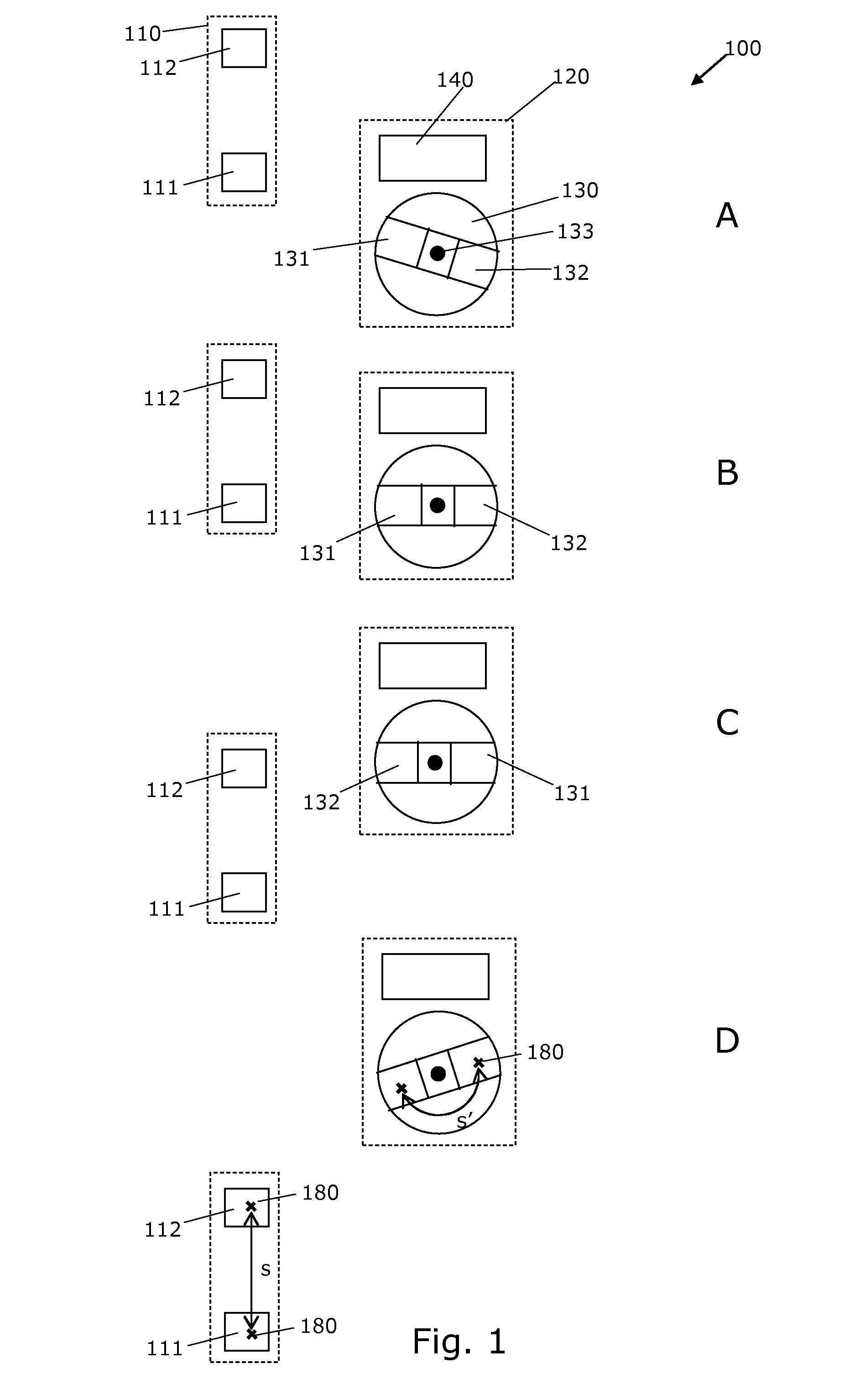
[0026]In an embodiment the arc length between geometric centres of the first and second driving poles of the first part is equal to, or substantially equal to the arc length between magnetic centres of two poles of the induction magnet, so that motion of the first and second driving poles by an arc length cause angular motion of the induction magnet by the same or substantially the same arc length measured between magnetic centres of two poles of the induction magnet. By matching the distances between driving poles and induction poles it is possible to obtain a gearing between travelling distance of the driving poles and the arc length between induction magnets, e.g. a gearing of one-to-one, two-to-one or one-to-two or other gearing of any other ratio. Thereby, it is possible to control the angular rotation of the induction magnet relative to the driving poles so as to obtain an optimal synchronisation and, thereby, optimal magnetic induction in the coil.

Problems solved by technology

Furthermore, the first driving pole does not disturb the magnetic flux towards the coil which is generated by the induction magnet and consequently, the first driving pole does not reduce the efficiency of the generator.

Method used


Image

  • Induction generator for a bi-cycle
  • Induction generator for a bi-cycle
  • Induction generator for a bi-cycle

Examples


Embodiment Construction

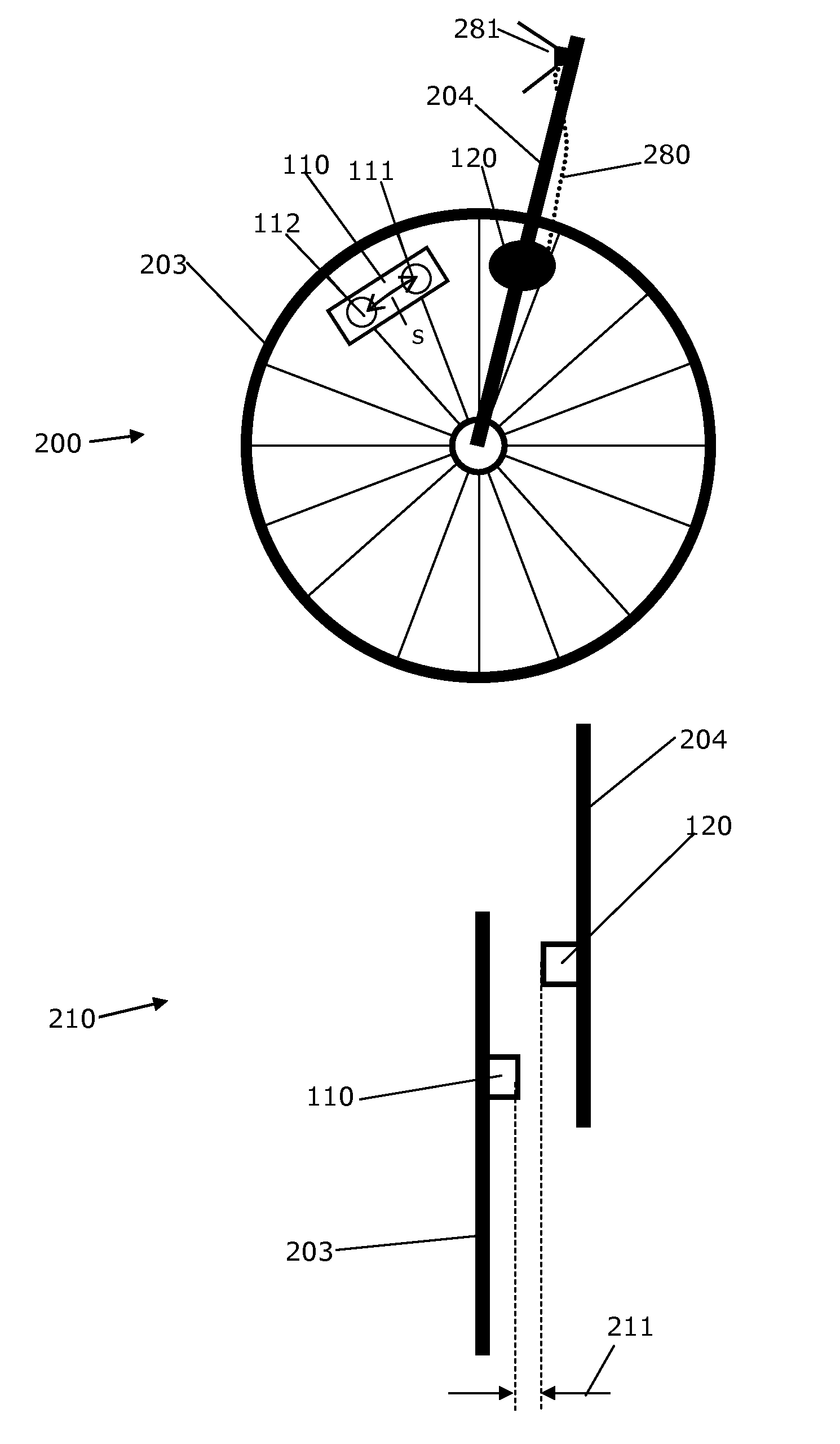
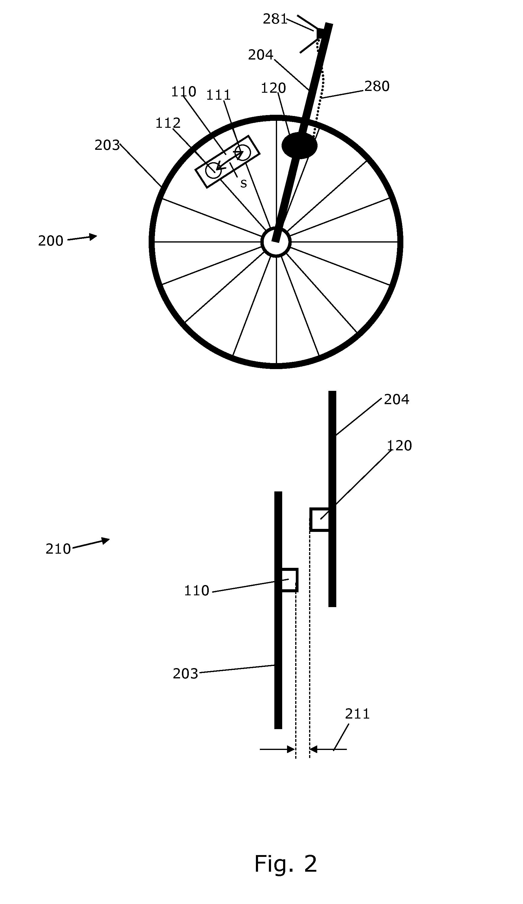
[0060]FIG. 1A shows an induction generator 100 for a vehicle for generating electric current. The generator comprises first and second parts 110,120 where the first part is normally mounted on a moveable part of the vehicle and the second part 120 is normally mounted on a stationary part of the vehicle.

[0061]The first part 110 comprises first and second magnetic poles 111, 112 of opposite magnetic polarities, e.g. the first pole may be a north pole and the second pole may be a south pole.

[0062]The second part 120 comprises an induction magnet 130 with first and second magnetic poles 131,132 of opposite magnetic polarities and a coil 140.

[0063]The coil may be a solenoid or other coil with windings of electrically conducting wire arranged to be subjected to the magnetic field of the induction magnet 130 so as to generate an electric current. The electric current may supplied via output wires of the coil to a lamp of the vehicle or other electrical consumers.

[0064]The induction magnet ...


PUM


Abstract

The invention provides a generator for a bicycle. The generator has one or more driving magnets fixed to a wheel of the bicycle and an induction structure that is fixed to a frame part of the bicycle. The induction structure comprises an induction magnet and a coil. A fixture allows fixing of the driving magnets at locations where they, during operation of the bicycle, repeatedly moves towards and away from the induction magnet. The generator comprises means for reorienting the induction magnet so that it is optimally oriented when a driving magnet approaches. Such means comprises a first driving magnet or a structure of magnetisable material which is magnetisable by the driving magnet.

Description

FIELD OF THE INVENTION[0001]The invention relates to an induction generator, in particular to an induction generator for vehicles such as bi-cycles.BACKGROUND OF THE INVENTION[0002]Generators or dynamos used for bicycles are well known. Several different variants of generators exist, ranging from very simple dynamos where a multiple pole permanent magnet is rotated relative to a single coil via a small wheel in frictional engagement with the rim of the tire of the bicycle. Other types of generators are based on magnets which are attached directly to the wheel or tire and which induces a current in a coil which is attached to the frame of the bicycle. Yet another type of generator is based on simple multiple pole generators which are arranged in the hub of the front wheel.[0003]WO 2009015910 discloses a generator for a bicycle. The generator has a driving magnet fixed to a wheel of the bicycle and an induction structure which is fixed to the frame of the bicycle. The induction struct...

Claims


Application Information

Patent Timeline
Patent Type & Authority Applications(United States)
IPC IPC(8): H02K7/18
CPCB62J6/06B62J6/20H02K41/03H02K7/1869H02K21/028H02K7/1846
Inventor PEDERSEN, TROELS
Owner REELIGHT
Learn More