
Multi-phase switching regulator and driver circuit and control method thereof

a multi-phase switching and driver circuit technology, applied in the direction of electric variable regulation, process and machine control, instruments, etc., can solve the problems of system crash or other problems, output voltage undershoot still occur, and undershoot, so as to reduce the gain of the current balance signal, and reduce the gain of the current balance circuit

Inactive Publication Date: 2012-07-12
RICHTEK TECH
View PDF5 Cites 37 Cited by
  • Summary
  • Abstract
  • Description
  • Claims
  • Application Information

AI Technical Summary

Problems solved by technology

This causes an undershoot in the output voltage and easily result in system crash or other problems.
Thus, output voltage undershoot will still occur because there is a limit for the power stages remain operating to ramp up their currents.
Consequently, the output current, which is the sum of all inductor currents of all phases, is not sufficient to support what is required by the load, and hence an output voltage undershoot often occurs during such transition period to cause system crash or other problems.
It is not flexible to force the duty ratios to be increased or decreased in this manner, and the output voltage undershoot still cannot be completely avoided.

Method used


Image

  • Multi-phase switching regulator and driver circuit and control method thereof
  • Multi-phase switching regulator and driver circuit and control method thereof
  • Multi-phase switching regulator and driver circuit and control method thereof

Examples


Embodiment Construction

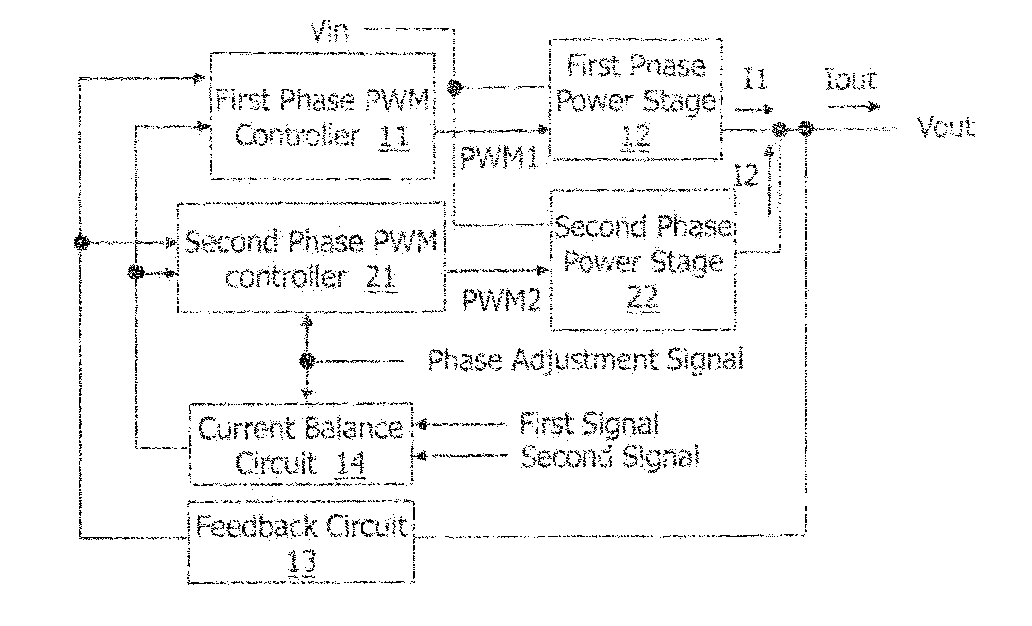
[0033]The basic concept of the present invention is as follows: when the multi-phase switching regulator switches between a light load condition and a heavy load condition (i.e., the number of active power stages need to be increased or reduced), the current balance circuit 14 is inactivated or the gain of the current balance circuit 14 is adjusted according to a phase adjustment signal, so that the output currents of the power stages which are about to be activated or inactivated are increased or decreased gradually, to avoid output voltage undershoot that will adversely affect the operation of the system.

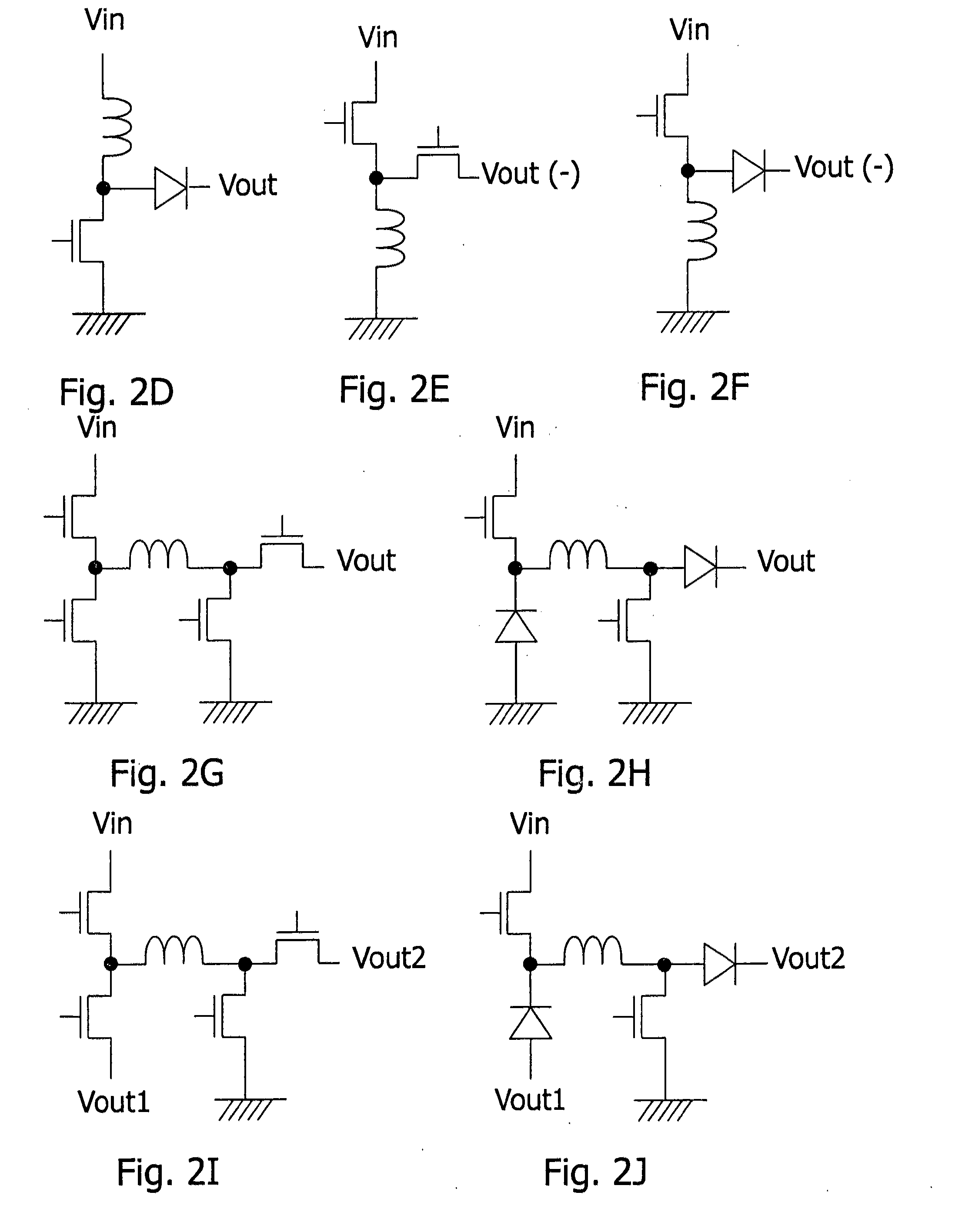
[0034]FIG. 3 shows an embodiment of the present invention, illustrating a basic configuration. In this embodiment, the first phase power stage 12 and the second phase power stage 22 may be, for example but not limited to, a synchronous or asynchronous buck converter, boost converter, inverting converter, or buck-boost converter as shown in FIG. 2A-2J. For simplicity in explaining ...


PUM


Abstract

The present invention discloses a multi-phase switching regulator, a driver circuit of a multi-phase switching regulator, and a control method of a multi-phase switching regulator. The multi-phase switching regulator includes: at least two power stages, switching power transistors in the power stages to convert an input voltage to an output voltage according to pulse width modulation (PWM) signals generated by corresponding PWM controllers respectively; and a current balance circuit, generating a current balance signal according to the current of the corresponding power stage and a phase adjustment signal to averagely distribute current over the active power stages. In the present invention, the gain of the current balance circuit is adjustable, to avoid or reduce output voltage overshoot and undershoot when the phase number changes, while the current balance function is still achieved in normal operation.

Description

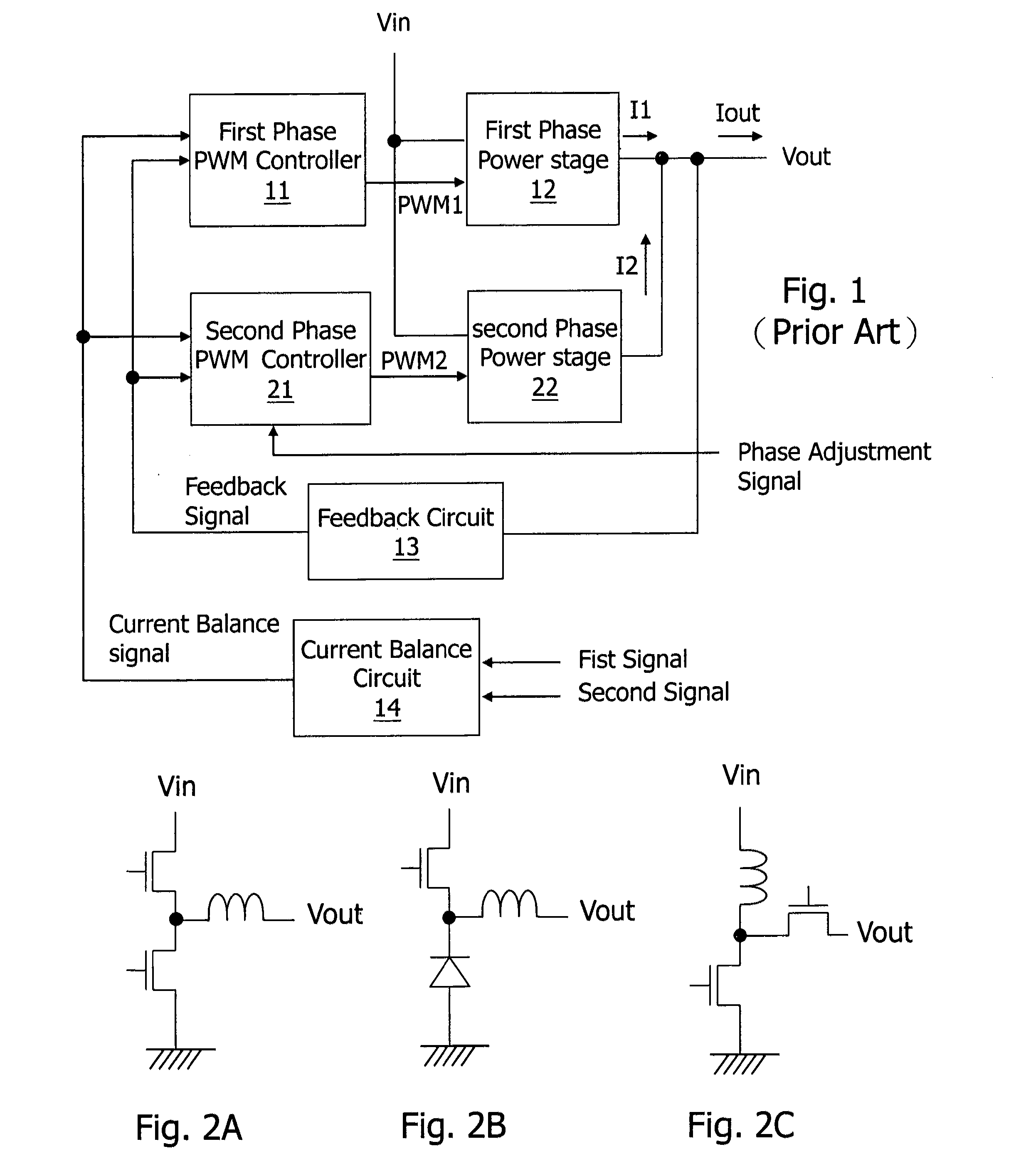
CROSS REFERENCE[0001]The present invention claims priority to TW 100100864, filed on Jan. 10, 2011.BACKGROUND OF THE INVENTION[0002]1. Field of Invention[0003]The present invention relates to a multi-phase switching regulator, a driver circuit of a multi-phase switching regulator and a control method of a multi-phase switching regulator, in particular to such multi-phase switching regulator, driver circuit and control method wherein the gain of a current balance circuit can be adjusted to avoid voltage overshoot and undershoot when the phase number of power stages is increased or decreased.[0004]2. Description of Related Art[0005]FIG. 1 shows a schematic diagram of a prior art multi-phase switching regulator. As shown in FIG. 1, a first phase PWM (pulse width modulation) controller 11 and a second phase PWM controller 21 respectively output a signal PWM1 and a signal PWM2 to control corresponding power transistors of a first phase power stage 12 and a second phase power stage 22 so ...

Claims


Application Information

Patent Timeline
Patent Type & Authority Applications(United States)
IPC IPC(8): G05F1/10
CPCH02M2003/1586H02M3/1584H02M3/1586
Inventor CHANG, YU-WEICHENG, YUAN-HUANGWANG, TING-HUNGLEE, CHIA-JUNGCHENG, CHUNG-SHENG
Owner RICHTEK TECH
Learn More