Electrophoretic display

a technology of electrophoretic display and display screen, applied in the field of electrophoretic display, can solve the problems of low production efficiency, lack of structure integrity and depth control, and certain disadvantages of continuous liquid phase structure, and achieve the effect of improving mechanical properties and structural integrity of film structur

Active Publication Date: 2012-07-12
E INK CALIFORNIA
View PDF5 Cites 56 Cited by
  • Summary
  • Abstract
  • Description
  • Claims
  • Application Information

AI Technical Summary

Benefits of technology

[0019]Using the film structure, a liquid composition is filled into individual microcups and the filled microcups are top-sealed. The size of the microcups can be predetermined and controlled. In addition, the microcup wall is in fact a built-in spacer to keep the top and bottom substrates apart at a fixed distance. The mechanical properties and structural integrity of the film structure are significantly improved. Furthermore, the use of the film structure eliminates the need of an edge seal adhesive required in the formation of a display panel. More importantly, the microcup-based film structure enables a format flexible manufacturing process wherein the process produces a continuous output of the film structure in a large sheet format which can be cut into any desired sizes afterwards.

Problems solved by technology

However, such a continuous liquid phase structure suffers certain disadvantages.
For example, it lacks structure integrity and depth control, especially when the plates are flexible substrates.
In addition, this type of structure is not format flexible for production and, if hard surface plates are involved, batch manufacturing is required which results in low production efficiency.
It could be challenging to control the size of the microcapsules to be within a desired range.
In addition, the capsule wall usually does not provide good mechanical support for structural integrity, especially with flexible substrates.
Material selection is another issue with the microencapsulation technique.
In many cases, extra chemical(s) are necessary to stabilize the dispersed phase; the extra chemical(s), however, could be detrimental to the final product.

Method used


Image

  • Electrophoretic display
  • Electrophoretic display
  • Electrophoretic display

Examples


Embodiment Construction

I. Film Structure

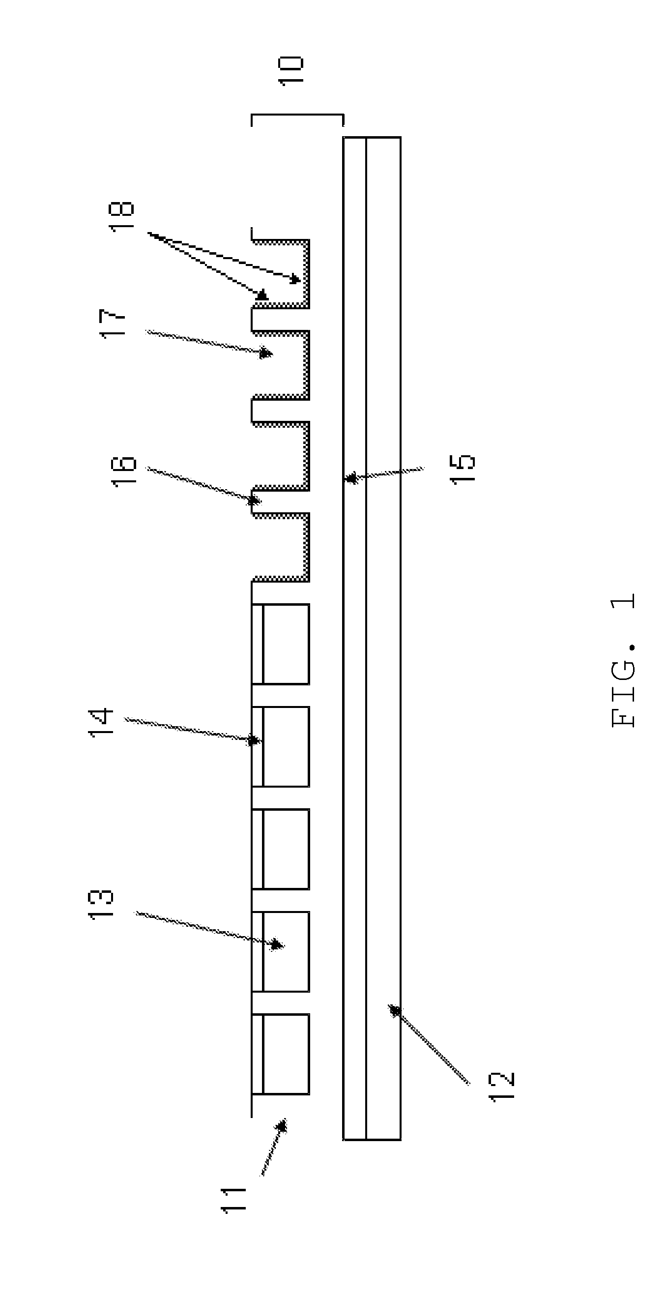
[0020]FIG. 1 illustrates the film structure (10), a electrophoretic display, which comprises one or more microcups (11). The microcups comprise partition walls (16) and top openings (17). The film structure (10) may be formed on a substrate layer (12) which may optionally comprise an electrode layer (not shown). There may also be an optional primer layer (15) between the microcups and the substrate layer (12). The microcups are filled with a liquid composition (13) and top-sealed with a polymeric sealing layer (14).

[0021]1. Formation of the Microcups

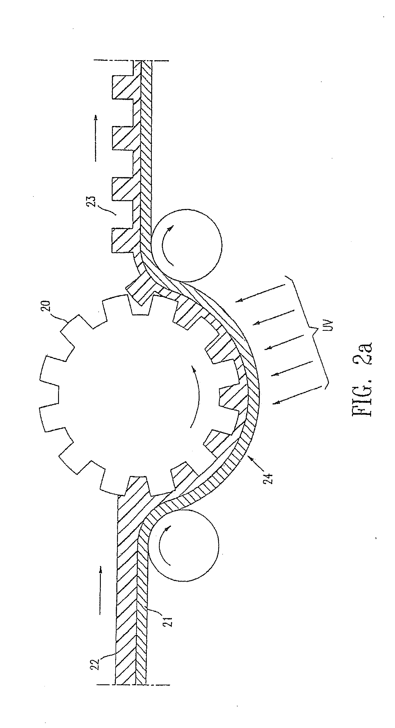
[0022](a) Microembossing

[0023]This processing step is shown in FIGS. 2a and 2b. A male mold (20) may be placed either above (FIG. 2a) or below (FIG. 2b) the web (24). The microcups may be formed on a flexible substrate layer (21). The substrate layer (21) may optionally comprise an electrode layer (not shown), which is suitable especially for display applications or other applications the operation of which involves the ...


PUM

PropertyMeasurementUnit
temperatureaaaaaaaaaa
depthaaaaaaaaaa

Abstract

The present invention is directed to an electrophoretic display comprising: (a) microcups comprising partition walls and top-openings; (b) an organic-based electrophoretic fluid filled in the microcups, wherein said fluid comprises charged pigment particles dispersed in a solvent; and (c) a top-sealing layer formed from a sealing composition to enclose the electrophoretic fluid within the microcups. The sealing composition comprises: (i) a water soluble polymer, (ii) a water-based suspension, a water-based dispersion, a water-based emulsion, or a water-based latex, each comprising a polymer; and (iii) water.

Description

[0001]This application is a continuation-in-part of U.S. application Ser. No. 11 / 774,773, filed Jul. 9, 2007; which claims the benefit of U.S. Provisional Application No. 60 / 831,779, filed Jul. 18, 2006. The above-identified applications are incorporated herein by reference in their entirety.BACKGROUND OF THE INVENTION[0002]Various structures with peripheral plates or walls containing a liquid component were previously known. For example, a liquid component may be filled between two parallel or near-parallel surfaces and, in such a case, the liquid component is present in a continuous form. The two plates may be edge sealed first with fill holes for subsequent filling of the liquid component. Alternatively, the liquid component may be dropped on one of the two plates (before or after application of the edge sealing adhesive), followed by placing a second plate on top of the first plate to contain the liquid component between the two plates. In some cases, spacers may be present in t...

Claims


Application Information

Patent Timeline
Patent Type & Authority Applications(United States)
IPC IPC(8): G02F1/167G02F1/1679
CPCC09K19/544C09K2019/546G02F2001/1672G02F1/1341G02F1/167G02F1/133377G02F1/1681G02F1/1679A61K9/7092A61N1/303A61N1/0448
Inventor ZANG, HONGMEICHEN, HUI
Owner E INK CALIFORNIA
Why Eureka
Try Eureka