Method and apparatus for in-situ testing, fitting and verification of hearing and hearing aids

a technology for hearing aids and in-situ testing, which is applied in the direction of electrical devices, deaf aid adaptation, etc., can solve the problems of not producing a flat insertion gain for users, not considering the individual size differences of pina and ear canal, and less accurate fitting

Active Publication Date: 2012-07-12
OTOTRONIX
View PDF3 Cites 28 Cited by
  • Summary
  • Abstract
  • Description
  • Claims
  • Application Information

AI Technical Summary

Benefits of technology

[0022]The invention makes it possible to precisely obtain hearing aid parameters for a user by factorizing the individual ear size into the fitting procedure. It has the potential to maximize the hearing aid performance for the user. Also, it makes it possible to fit a hearing aid without a separate test with separate equipment, such as a stand-alone audiometer or real-ear measurement system. Other aspects and advantage of the invention will become apparent from the following detailed description taken in conjunction with the accompanying drawings which illustrate, by way of example, the principle of the invention.

Problems solved by technology

It is well known that a hearing aid with flat frequency response, when worn in or behind the ear, does not produce a flat insertion gain for a user.
However, this correction does not consider the individual size differences of the pina and ear canal.
These differences may demand different gain setting for the user, and if not considered, may result in less accurate fitting.
The individual size difference of the pina and canal is not taken into account, largely due to technical difficulty.
The fitting may be less accurate if such interactive procedure is not employed.
However, this kind of verification may actually be misleading when the user has significant size difference in the pina and canal from the average.
Another problem in hearing aid fitting is that individual listening preference to sound level and frequency equalization are not taken into considerations in fitting formulae and the real ear verification procedures.
The problem is that aided functional gain measurement has to be done by the free field with testing sounds delivered to both ears simultaneously.
However, it is sometimes difficult to determine which of the two hearing aids is providing more benefit.
From the foregoing, it can be seen that there are still longstanding problems in the field of hearing devices and procedures for hearing aid fitting that those with skill in the art have been unable to solve.

Method used


Image

  • Method and apparatus for in-situ testing, fitting and verification of hearing and hearing aids
  • Method and apparatus for in-situ testing, fitting and verification of hearing and hearing aids
  • Method and apparatus for in-situ testing, fitting and verification of hearing and hearing aids

Examples


Embodiment Construction

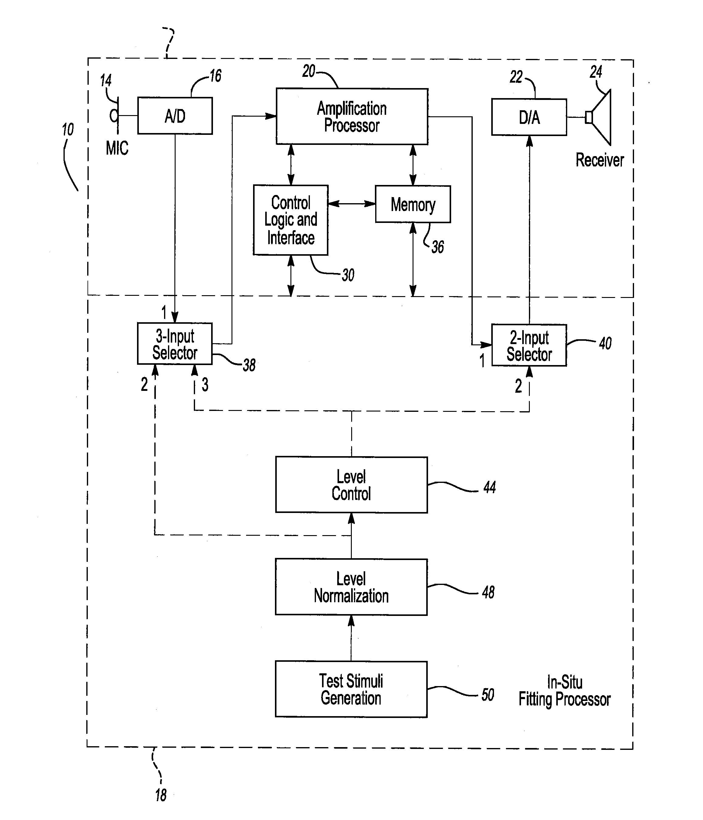
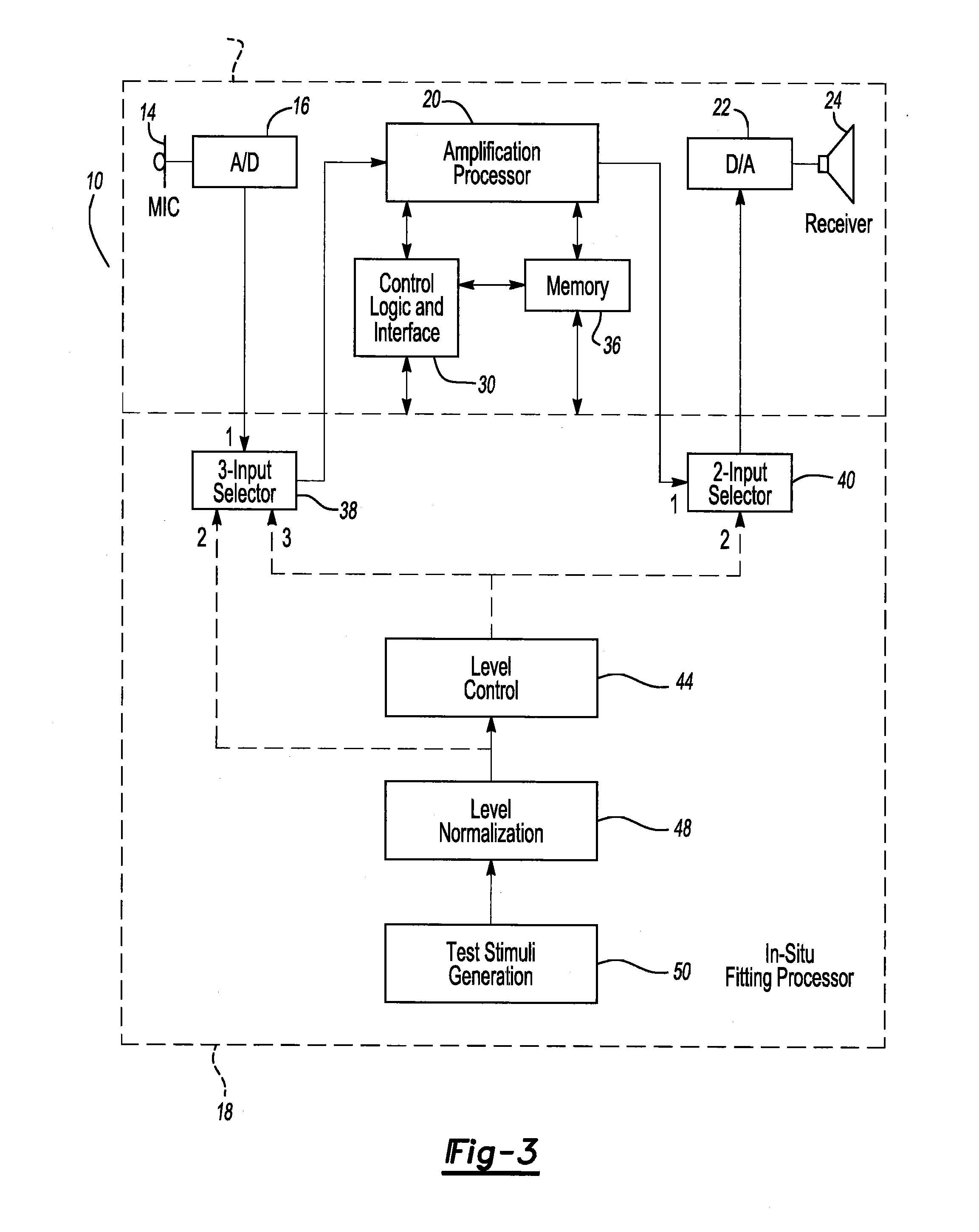
[0036]As known in the art, a microphone is an acoustic-to-electric transducer or sensor that converts sound into an electrical signal. Most microphones today use electromagnetic induction, piezoelectric generation, or light modulation, to produce an electrical voltage signal from mechanical vibration. While any of these types of microphones may be used in the present invention, a condenser microphone is preferred.

[0037]For a given sound input, most usually measured in decibels (dB), a microphone manufacturer will know the electrical signal produced thereby, normally in the millivolt (mV) range. This value is sometimes, when converted into digital units via an analog to digital converter, referred to in the art in terms of ADC units per Pascal. Because most microphones are calibrated to tight standards, for a given ADC unit, the sound pressure (SP) in decibels will be known to ±3 dB.

[0038]The present invention not only uses this property, but does so in a novel and unique way to prov...


PUM


Abstract

An improved multi-function hearing aid having in-situ testing, fitting and verification functions is disclosed which solves problems long standing in the art of hearing aid fitting dealing with individual size differences in the size of the pina and ear canal of the user, individual preference to sound level and frequency variation, and verification procedures.

Description

BACKGROUND OF THE INVENTION[0001]This application is a continuation of Patent Cooperation Treaty application Serial No. PCT / US2010 / 001389, filed on May 11, 2010, which claims priority from provisional application Ser. No. 61 / 215,786, filed May 11, 2009 under 35 U.S.C. §111(b). Both applications are hereby incorporated by reference in their entirety.FIELD OF THE INVENTION[0002]The present invention relates to a method of testing hearing, hearing tests, hearing aid operation, hearing aid fitting, and fitting verification.DESCRIPTION OF THE RELATED ARTS[0003]It is well known that a hearing aid with flat frequency response, when worn in or behind the ear, does not produce a flat insertion gain for a user. For an average user, the correction needed for hearing aid response in order to produce a flat insertion gain can be achieved by the so-called CORFIG (COupler Response for Flat Insertion Gain). However, this correction does not consider the individual size differences of the pina and e...

Claims


Application Information

Patent Timeline
Patent Type & Authority Applications(United States)
IPC IPC(8): H04R29/00
CPCH04R25/70
Inventor HOU, ZEZHANGLINDSEY, LEON ALEKSANDER
Owner OTOTRONIX
Why Eureka
Try Eureka