Image coding method, image decoding method, image coding apparatus, image decoding apparatus, and image coding and decoding apparatus
a technology of image coding and probability information, applied in the field of image coding methods, image decoding methods, image coding apparatuses, image coding and decoding apparatuses, can solve the problems of insufficient coding efficiency of conventional arithmetic coding, inability to ensure the accuracy and small update numbers of coded probability information for some contexts. achieve the effect of increasing the accuracy of image coding efficiency
- Summary
- Abstract
- Description
- Claims
- Application Information
AI Technical Summary
Benefits of technology
Problems solved by technology
Method used
Image

Examples
embodiment 1
[0098]Embodiment 1 relating to an image coding method and an image coding apparatus according to the present invention is described with reference to FIG. 3 to FIG. 8.
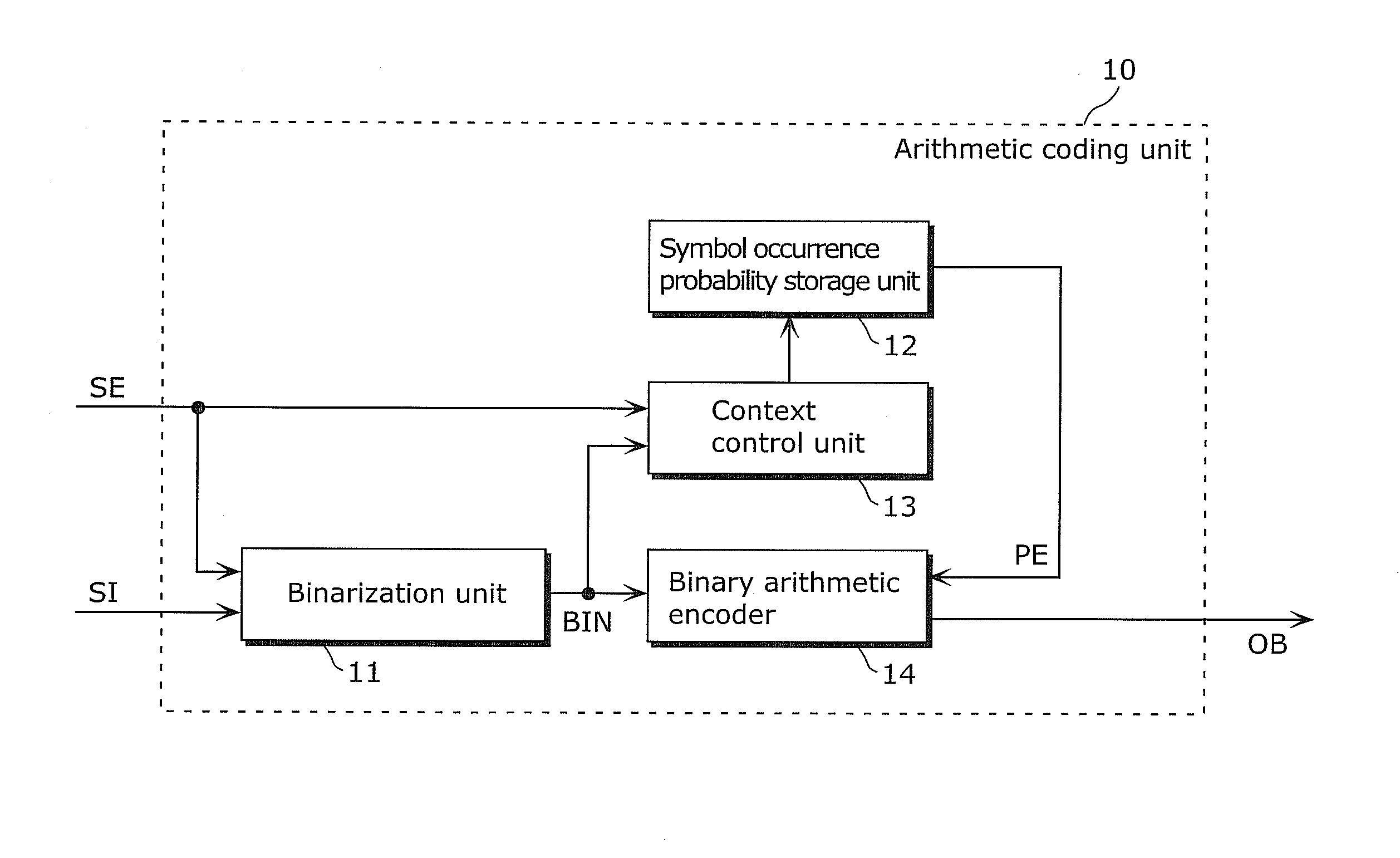
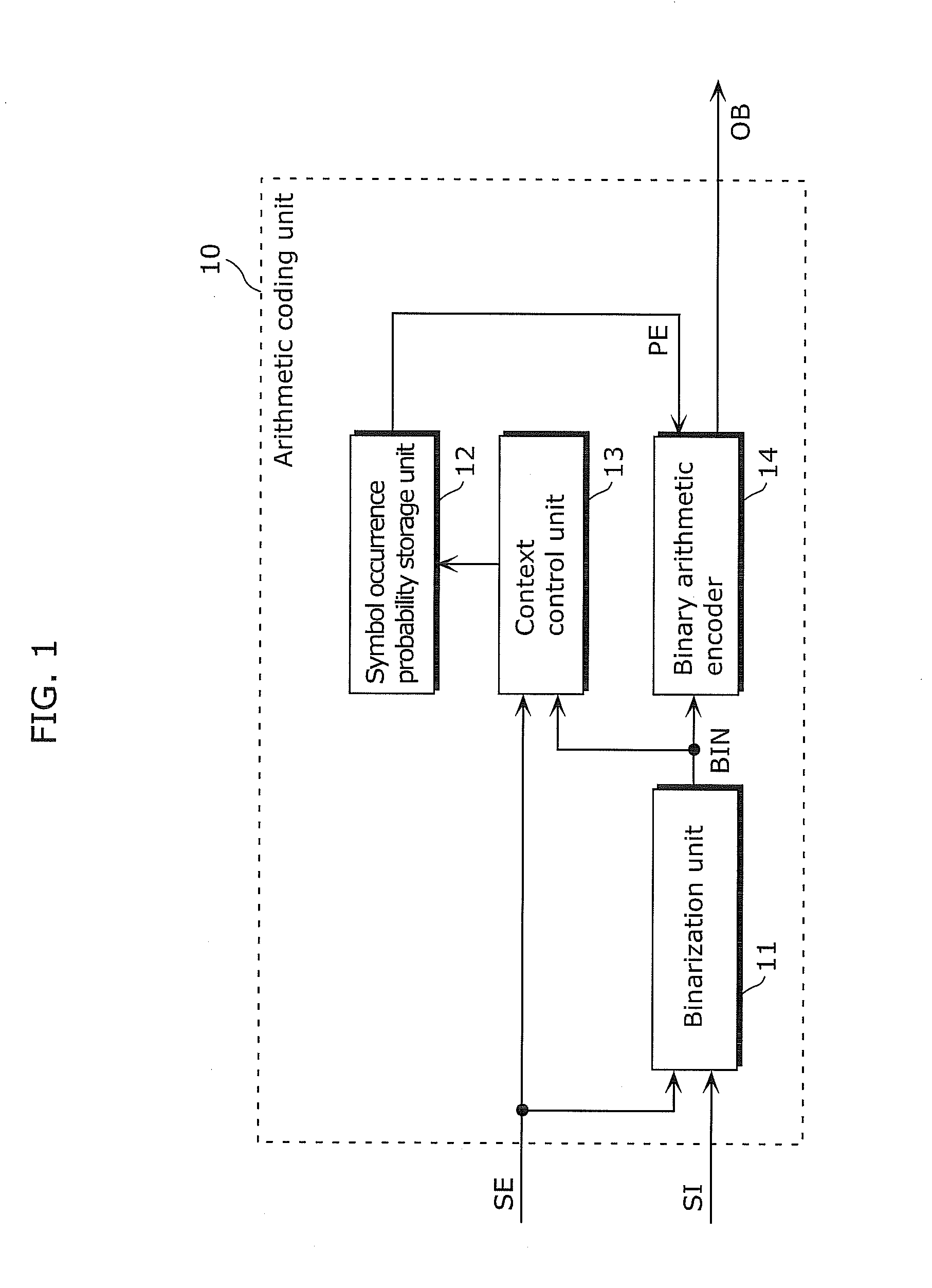
[0099]The image coding method according to the present invention particularly relates to an arithmetic coding method as an example of entropy coding among compression coding composed of prediction, transform and quantization, entropy coding, and the like performed on a current signal to be coded of an image. In addition, the image coding apparatus according to the present invention is configured to include a prediction unit, a transform and quantization unit, and an arithmetic coding unit (entropy coding unit) which executes the arithmetic coding method. The overall structure of the image coding apparatus is described later.
(Outline of Embodiment 1)
[0100]The outline of an arithmetic coding method and an arithmetic coding unit according to Embodiment 1 is firstly described. Here, a description is given of a case where a...
operation example 1
[0141]In FIG. 8, the context block classification control unit 105 firstly determines the coefficient position based on the signal type information SE, and determines whether the coefficient position of the input signal SI which is the current signal to be coded is included in the low frequency area or in the high frequency area (Step S202).
[0142]Here, as described above, the quantized coefficients correspond to signals generated by performing frequency transform and quantization on the image, and the coefficient positions correspond to the frequency components in the frequency transform. For example, in the schematic diagram shown as each of (a) to (c) in FIG. 11, the quantized coefficients corresponding to the low frequency components are located at the upper left portion, and the quantized coefficients corresponding to the high frequency components are located at the lower right portion. More specifically, in an exemplary case where a coefficient position is one of coefficient po...
operation example 2
[0150]In FIG. 9, the context block classification control unit 105 firstly determines, based on the signal type information SE, a coefficient position of an input signal SI which is the current signal to be coded, and determines whether the input signal SI is included in the low frequency area or in the high frequency area (Step S202). Here, the determination method is the same as in Operation Example 1.
[0151]In the case where the input signal SI is a coefficient corresponding to a low frequency component (YES in Step S202), the context block classification control unit 105 selects a context table set for the block size, and outputs the information as a control signal CTRS. Here, in the context table, indices ctxIdx for the low frequency components are set further based on the conditions respectively determined based on the coefficient positions. Accordingly, as a result, the context control unit 103 sets the context according to the block size and the coefficient position (Step S20...
PUM
 Abstract
Description
Claims
Application Information
 - R&D
- Intellectual Property
- Life Sciences
- Materials
- Tech Scout
- Unparalleled Data Quality
- Higher Quality Content
- 60% Fewer Hallucinations
Browse by: Latest US Patents, China's latest patents, Technical Efficacy Thesaurus, Application Domain, Technology Topic, Popular Technical Reports.
© 2025 PatSnap. All rights reserved.Legal|Privacy policy|Modern Slavery Act Transparency Statement|Sitemap|About US| Contact US: help@patsnap.com