
Adhesive tape roll and method for manufacturing adhesive tape roll

Active Publication Date: 2012-07-12
NITOMS INC
View PDF2 Cites 3 Cited by
  • Summary
  • Abstract
  • Description
  • Claims
  • Application Information

AI Technical Summary

Benefits of technology

[0011]In order to achieve the above object, the present invention has some features described below. The invention according to claim 1 provides a method for manufacturing an adhesive tape roll which is obtained by winding an adhesive tape having an adhesive face formed on one face of a substrate such that the adhesive face is directed to a front side and in which cut lines for 
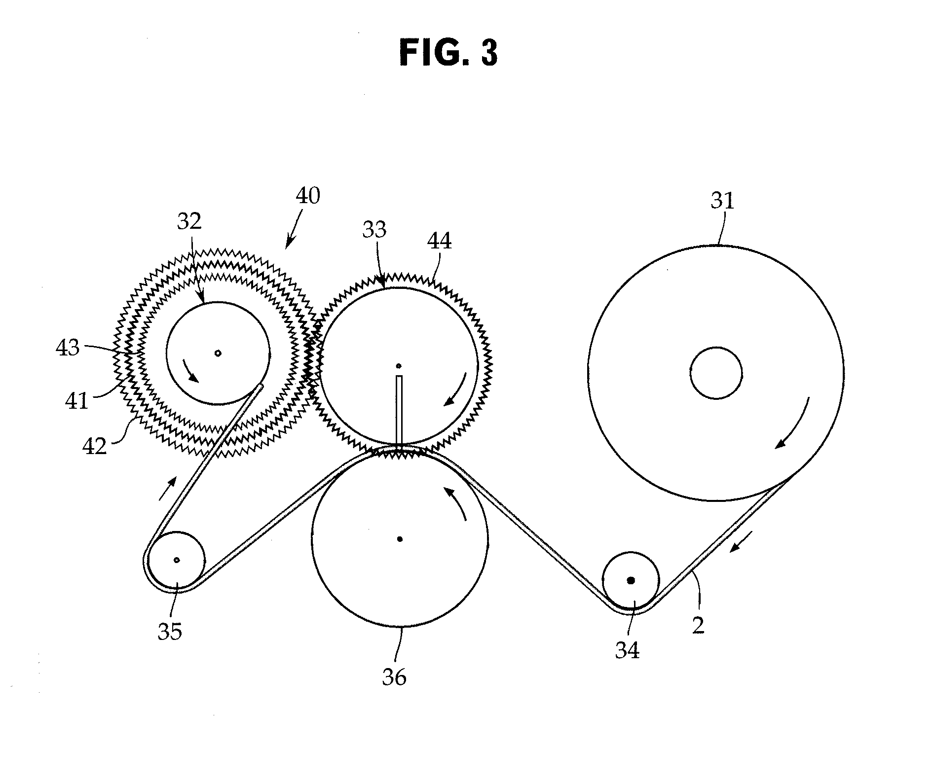
cutting are continuously formed in the adhesive tape at a predetermined interval along a feed direction of the adhesive tape, wherein a winding roller that winds the adhesive tape fed out from a mother roll and a cut-lines formation roller that is provided between the mother roll and the winding roller and forms the cut lines in the adhesive tape at the predetermined interval are provided, and the winding roller and the cut-lines formation roller are rotated in synchronization with each other via predetermined gears.
[0020]With the invention according to claim 2, a gear ratio of a gear on a side of the winding roller to a gear on a side of the cut-lines formation roller is one to one. In this manner, cut lines can be regularly formed at the same position in an overlapped state. Therefore, the deformation of an adhesive tape roll into an onion shape can be reliably prevented.
[0021]With the invention according to claim 3, a gear ratio of a gear on a side of the winding roller to a gear on a side of the cut-lines formation roller is less than one to one. In this manner, an interval between cut lines is set at a position greater than 360° on the basis of a circumferential length. Therefore, when a used adhesive face and a part of an adhesive tape including a boundary part are removed, an unused adhesive tape roll can be exposed over its whole circumference.
[0022]With the invention according to claim 4, a gear ratio of a gear on a side of the winding roller to a gear on a side of the cut-lines formation roller is less than one to one. In this manner, an interval between cut lines is set at a position less than 360° on the basis of a circumferential length, and a previous used adhesive face remains at the tip end part of an unused adhesive tape face. Therefore, because adhesion at the tip end part of the unused adhesive tape face is reduced, a rail drawing phenomenon can be prevented.
[0023]With the invention according to claim 5, three types of gears having a gear ratio of one to one, less than one to one, and greater than one to one, respectively, are provided about one of the winding roller and the cut-lines formation roller and provided in such a manner as to be capable of selectively engaging with a gear of the other of the winding roller and the cut-lines formation roller. In this manner, three types of cut lines can be easily manufactured with a single apparatus.
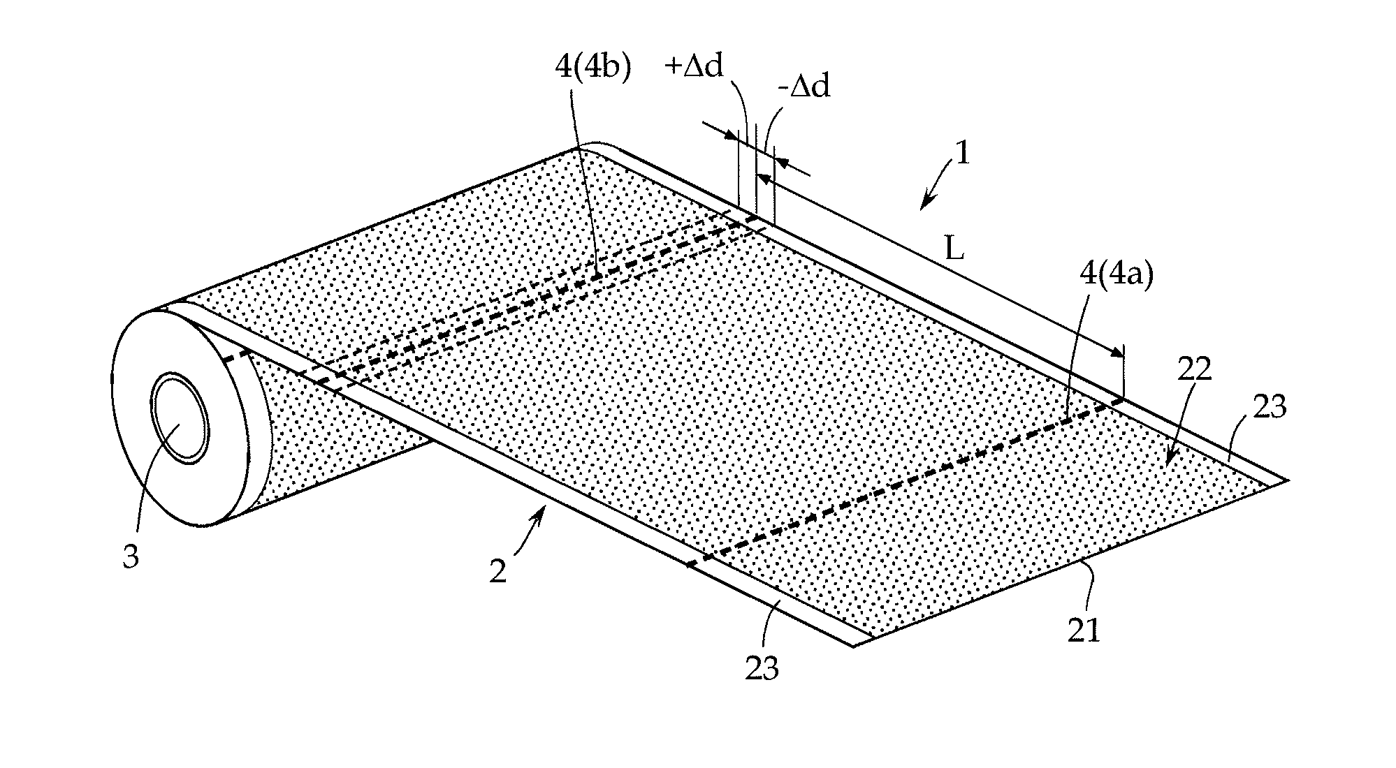
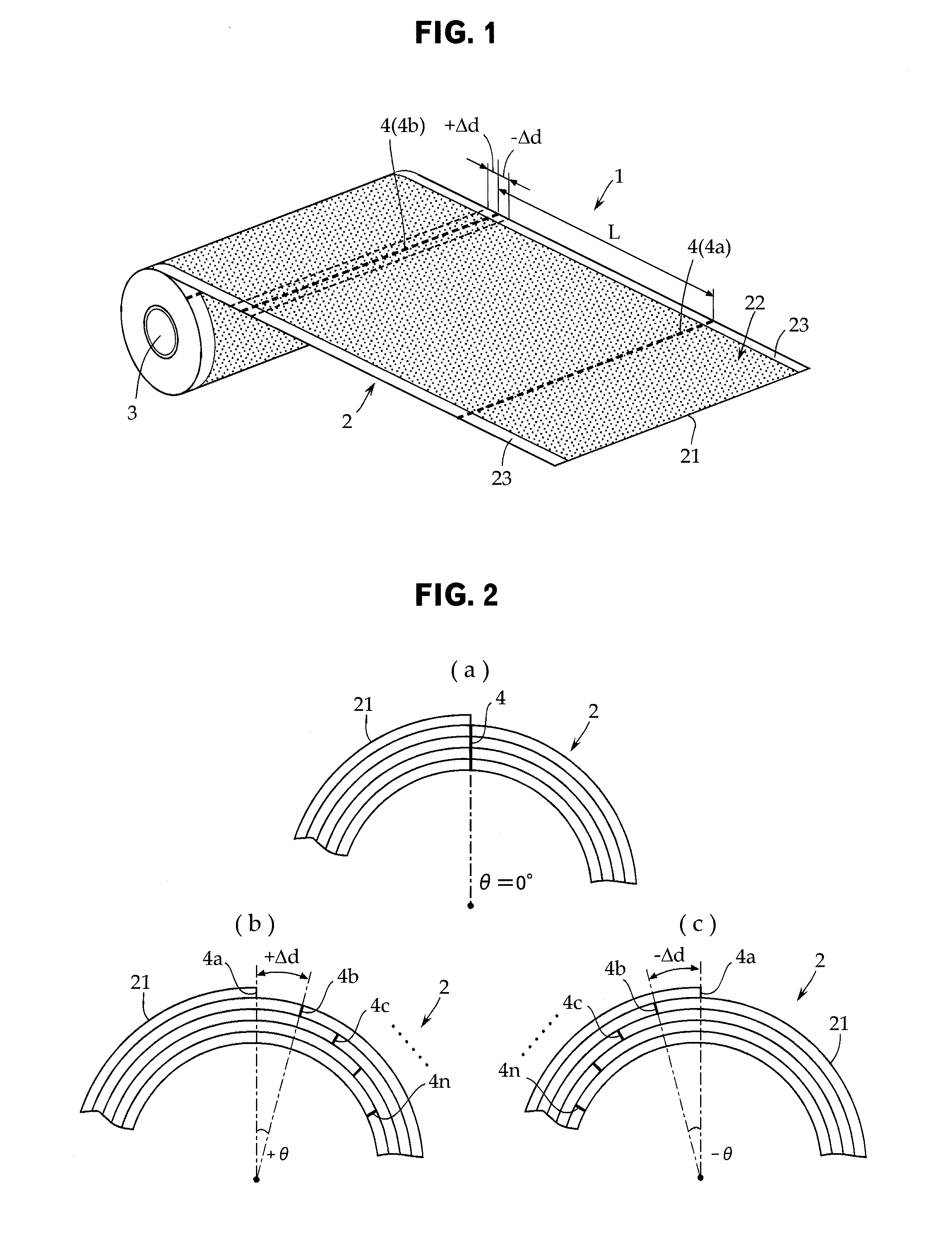
[0024]With the invention according to claim 6, when a single circumferential length of the adhesive tape of an n-th (where n is a positive integer) turn is Ln, a radius of the winding core is r, a thickness of the adhesive tape is t, a deviation between cut lines of an n-th layer and cut lines of an n+1-th layer is Δd, and an interval between the cut lines of the adhesive tape of the n-th turn and the cut lines of the n+1-th layer is expressed by an angular difference θ, following Equations 1 to 3 are satisfied:
Ln=2π{r×(n−1)×t}  Equation (1);
Ln+1=L×(360−θ) / 360  Equation (2); and
Ln+1=Ln+Δd  Equation (3).
[0025]In this manner, cut lines can be arbitrarily formed at a predetermined interval on the condition that the angular difference θ or the deviation Δd is made constant.
[0026]With the invention according to claim 7, the angular difference θ is in a rage of equal to or greater than 6° and equal to or less than 19°. When the angular difference θ is less than 6°, the deviation Δd becomes equal to or less than 2 mm. Therefore, the reduction of adhesion cannot be prevented, which may cause a rail drawing phenomenon to occur. On the other hand, when the angular difference θ is greater than 19°, the deviation Δd becomes greater than 10 mm. Therefore, an unused adhesive tape must be wastefully torn off, which is economically disadvantageous.

Problems solved by technology

Because of this, the control of the adhesive tape becomes cumbersome correspondingly, and productivity is decreased due to the reduction of a conveyance speed or the like.

Method used


Image

  • Adhesive tape roll and method for manufacturing adhesive tape roll
  • Adhesive tape roll and method for manufacturing adhesive tape roll
  • Adhesive tape roll and method for manufacturing adhesive tape roll

Examples


example

[0058]Next, a more specific embodiment of the present invention will be described. The positions of the cut lines 4 were calculated on the condition that the radius r of the winding core 3 was 20 mm, the thickness t of the adhesive tape 2 was 0.1 mm, and the angular differences θ when the adhesive tape was wound by 90 turns were set to be equal to 0° (θ=0°), +12° (θ=12°), and −12° (θ=−12°).

[0059](When the angular difference θ is set to be equal to 0° (θ=0°))

[0060]When the angular difference θ is set to be equal to 0° (θ=0°), the length Ln at the first turn is 125.60 mm according to the equation Ln=2π{r×(n−1)×t}. Because the deviation Δd is not caused, the length L is gradually increased in proportion to the number of turns of the adhesive tape 2. Table 1 illustrates calculation results. According to the results, it is found that the cut lines 4 can be arranged at the same position when the length L is gradually made larger as the number of the turns increases.

TABLE 1circum-n-thferen...


PUM


Abstract

Disclosed is a technique of manufacturing an adhesive tape roll by which cut lines for cutting an adhesive tape can be regularly formed at a constant position. Provided are a winding roller (32) that winds the adhesive tape (2) fed out from a mother roll (31) and a cut-lines formation roller (33) that is provided between the mother roll (31) and the winding roller (32) and forms the cut lines (4) in the adhesive tape (2) at a predetermined interval. The winding roller (32) and the cut-lines formation roller (33) are rotated in synchronization with each other via predetermined gears (40).

Description

TECHNICAL FIELD[0001]The present invention relates to an adhesive tape roll for cleaning wound with its adhesive face directed to a front side, and more specifically, to a technique of forming cut lines for cutting for every single circumferential length.BACKGROUND ART[0002]It is difficult to completely remove hairs, dust, or the like twined around carpets, etc., by the suction of vacuum cleaners because fibers are intertwined with each other. In order to address this problem, adhesive tape rolls for cleaning are used as a method for removing foreign particles of this type.[0003]As illustrated in, for example, Patent Document 1, an adhesive tape roll is obtained by winding an adhesive tape having an adhesive part on one face of a substrate made of a sheet body like a paper such that the adhesive part is exposed to a front side. The adhesive tape roll is structured to rotate the adhesive face on a floor as an object face to be cleaned using a dedicated jig not illustrated, thereby fo...

Claims


Application Information

Patent Timeline
IPC IPC(8): B65H35/04B32B3/00B65H18/08
CPCA47L25/005B08B7/0028Y10T428/15B65H2701/18444C09J5/08B65H35/04Y10T156/1064
Inventor NUMAZU, YASUHIROOGAWA, TAKAHISA
Owner NITOMS INC
Features
  • Generate Ideas
  • Intellectual Property
  • Life Sciences
  • Materials
  • Tech Scout
  • Unparalleled Data Quality
  • Higher Quality Content
  • 60% Fewer Hallucinations
Learn More