Wireless ultrasound imaging system and method for wireless communication in an ultrasound imaging system

a wireless communication and ultrasound imaging technology, applied in the field of ultrasound imaging systems, can solve the problems of limited ultrasound data and/or patient or object image and the number of probes that can be coupled with the known ultrasound imaging system is limited in the number of cables that may be coupled with the system, and the amount of ultrasound data and/or the number of patients or objects that can be imaged at a given time by these systems

Inactive Publication Date: 2012-07-12
GENERAL ELECTRIC CO
View PDF3 Cites 42 Cited by
  • Summary
  • Abstract
  • Description
  • Claims
  • Application Information

AI Technical Summary

Benefits of technology

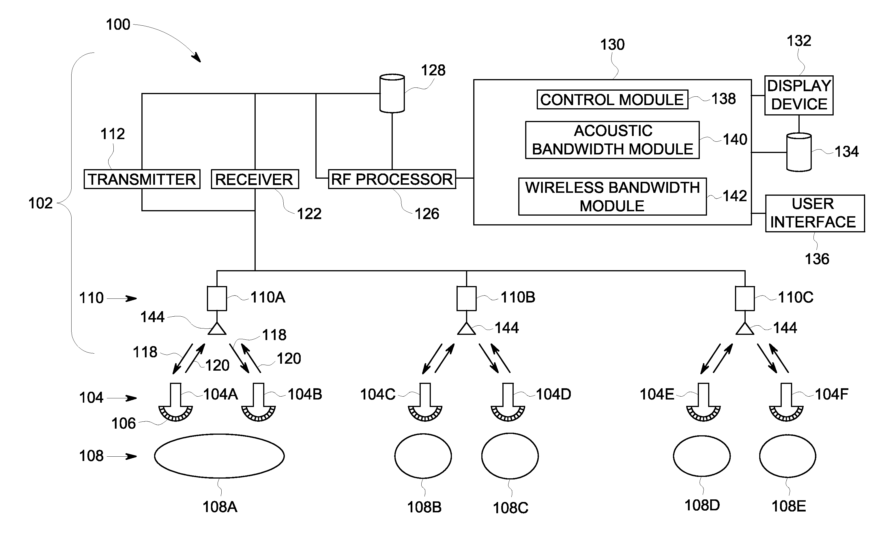
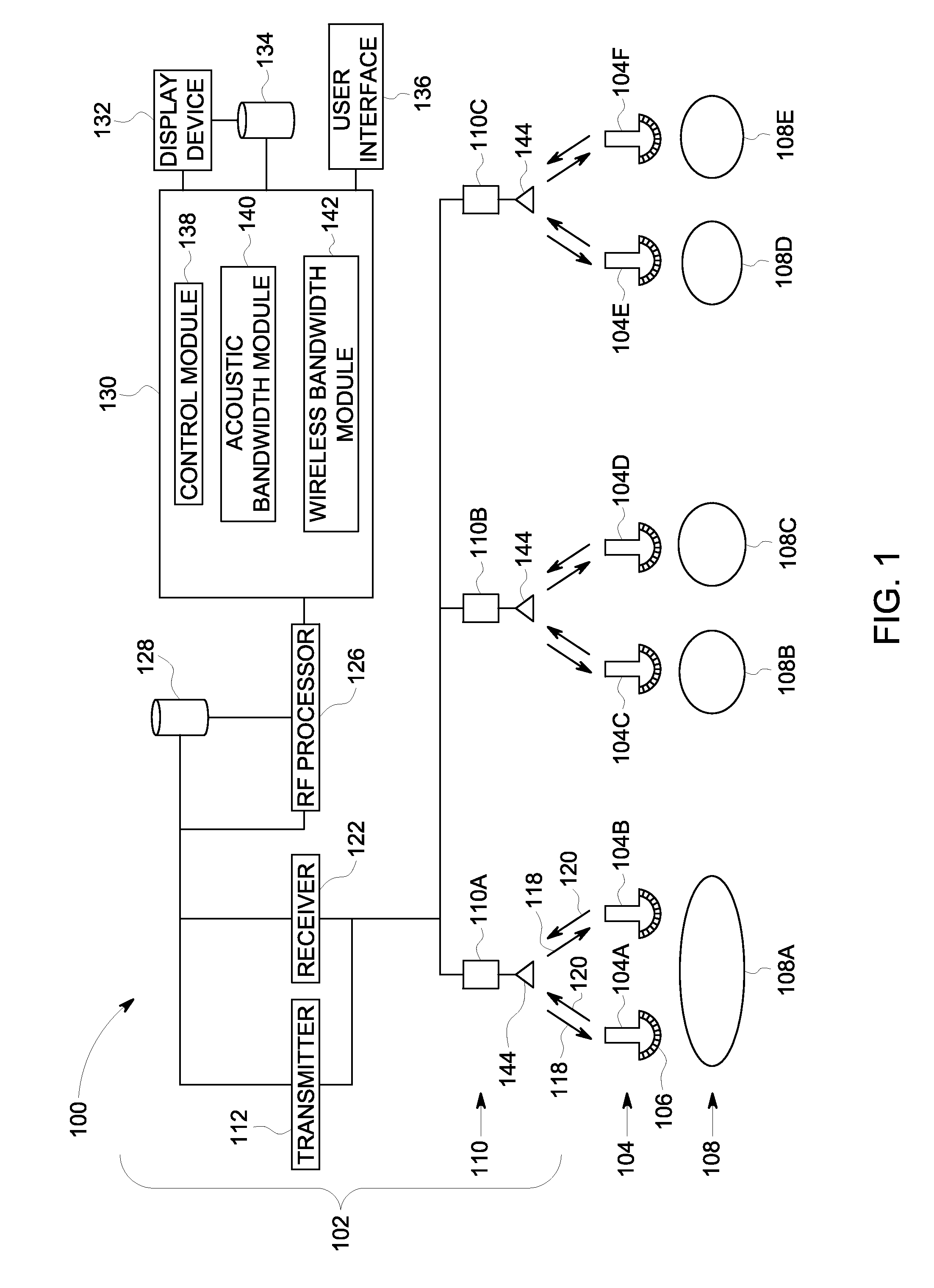
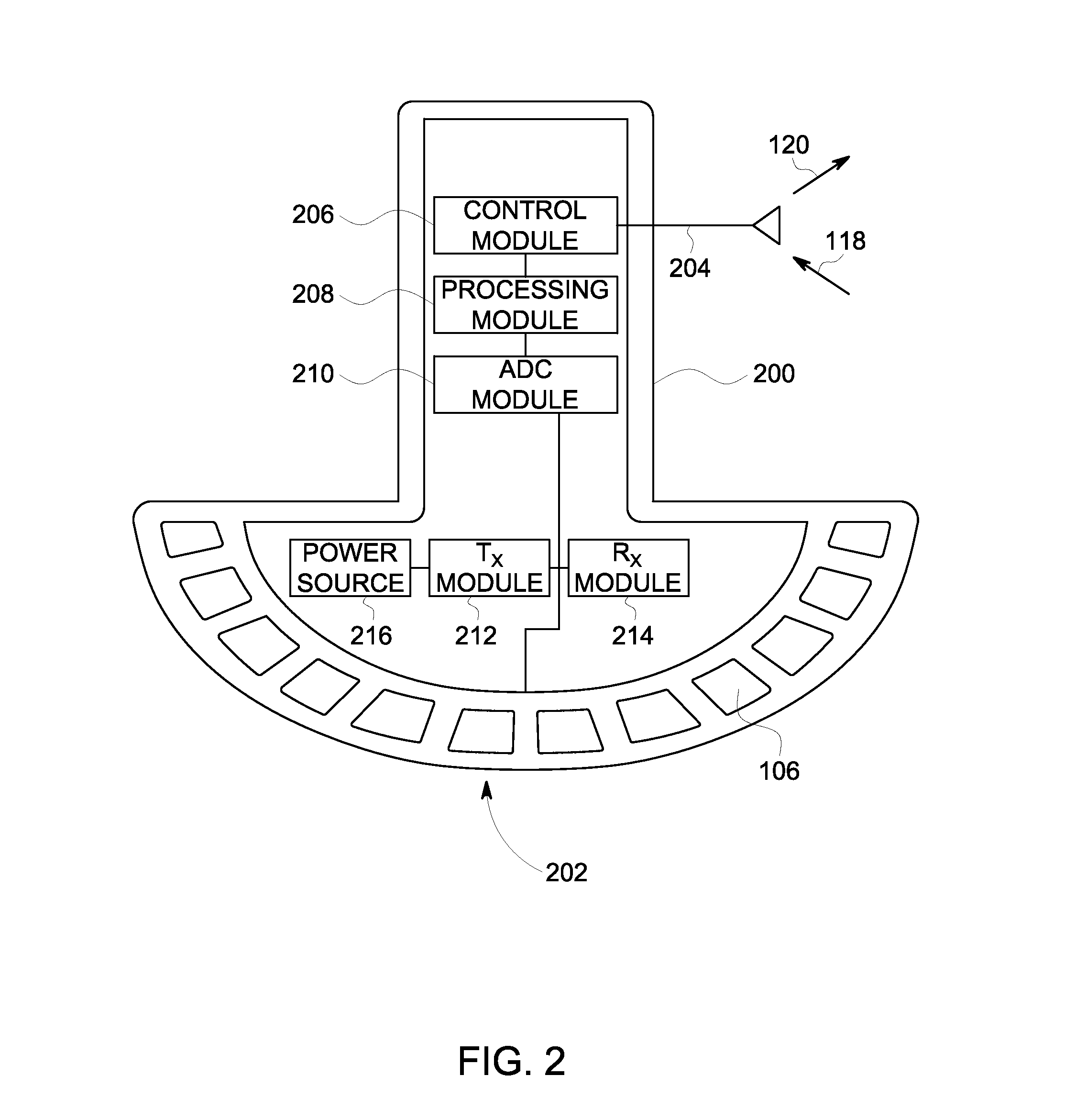
[0005]In accordance with one embodiment, a wireless ultrasound imaging system is provided. The system includes plural probes, at least one access point device, and a processing subsystem. Each of the probes has at least one transducer element that is configured to emit ultrasound pulses into one or more imaged bodies and receive echoes of the pulses. The probes are configured to generate ultrasound data based on the echoes and to wirelessly transmit the ultrasound data. The access point device is configured to wirelessly receive the ultrasound data from the probes. The processing subsystem is communicatively coupled with the at least one access point device. The processing subsystem receives the ultrasound data from the probes and creates one or more images based on the ultrasound data. In one aspect, a plurality of the probes is configured to concurrently acquire the ultrasound data.
[0006]In another e

Problems solved by technology

Some known ultrasound imaging systems are limited in the number of probes that can be coupled with the system.
Moreover, many of these systems permit only a single ultrasound probe to be connected to the system by a cable to acquire ultrasound data at a time.
The number of cables that may be coupled to the system may be limited.
As a result, th

Method used


Image

  • Wireless ultrasound imaging system and method for wireless communication in an ultrasound imaging system
  • Wireless ultrasound imaging system and method for wireless communication in an ultrasound imaging system
  • Wireless ultrasound imaging system and method for wireless communication in an ultrasound imaging system

Examples


Embodiment Construction

[0017]The foregoing summary, as well as the following detailed description of certain embodiments of the present invention, will be better understood when read in conjunction with the appended drawings. To the extent that the figures illustrate diagrams of the functional blocks of various embodiments, the functional blocks are not necessarily indicative of the division between hardware circuitry. One or more of the functional blocks (e.g., processors or memories) may be implemented in a single piece of hardware (e.g., a general purpose signal processor or random access memory, hard disk, or the like) or multiple pieces of hardware. Similarly, the programs may be stand alone programs, may be incorporated as subroutines in an operating system, may be functions in an installed software package, and the like. It should be understood that the various embodiments are not limited to the arrangements and instrumentality shown in the drawings.

[0018]As used herein, an element or step recited ...


PUM


Abstract

A wireless ultrasound imaging system includes plural probes, at least one access point device, and a processing subsystem. Each of the probes has at least one transducer element that is configured to emit ultrasound pulses into one or more imaged bodies and receive echoes of the pulses. The probes are configured to generate ultrasound data based on the echoes and to wirelessly transmit the ultrasound data. The access point device is configured to wirelessly receive the ultrasound data from the probes. The processing subsystem is communicatively coupled with the at least one access point device. The processing subsystem receives the ultrasound data from the probes and creates one or more images based on the ultrasound data. In one aspect, a plurality of the probes is configured to concurrently acquire the ultrasound data.

Description

BACKGROUND OF THE INVENTION[0001]The subject matter described herein relates generally to imaging systems, and more particularly, to ultrasound imaging systems.[0002]Ultrasound imaging systems are used in different applications to image different regions or areas (e.g., different organs) of patients or other objects. For example, an ultrasound imaging system may be utilized to generate images of organs, vasculature, heart or other portions of the body. The ultrasound imaging systems can include cables that mechanically and electrically connect ultrasound probes with the systems. The probes emit ultrasound pulses that back-scatter off of objects within the patient or object being imaged and may return to the probes as echoes. The echoes are converted into ultrasound data that is processed to form an image.[0003]Some known ultrasound imaging systems are limited in the number of probes that can be coupled with the system. For example, the number of ports in the system that are shaped t...

Claims


Application Information

Patent Timeline
IPC IPC(8): A61B8/14
CPCA61B8/4427A61B8/4472A61B8/585A61B8/54A61B8/4477G01S7/52082
Inventor HALMANN, MENACHEM
Owner GENERAL ELECTRIC CO
Why Eureka
Try Eureka