Eureka AIR delivers breakthrough ideas for toughest innovation challenges, trusted by R&D personnel around the world.

Surgical plate system and method

a plate system and plate technology, applied in the field of surgical plate system and method, can solve the problems of poor bone quality, poor graft quality, inadequate grafting technique, etc., and achieve the effect of reducing the head diameter

Active Publication Date: 2012-07-12
SPINECRAFT
View PDF36 Cites 32 Cited by
  • Summary
  • Abstract
  • Description
  • Claims
  • Application Information

AI Technical Summary

Benefits of technology

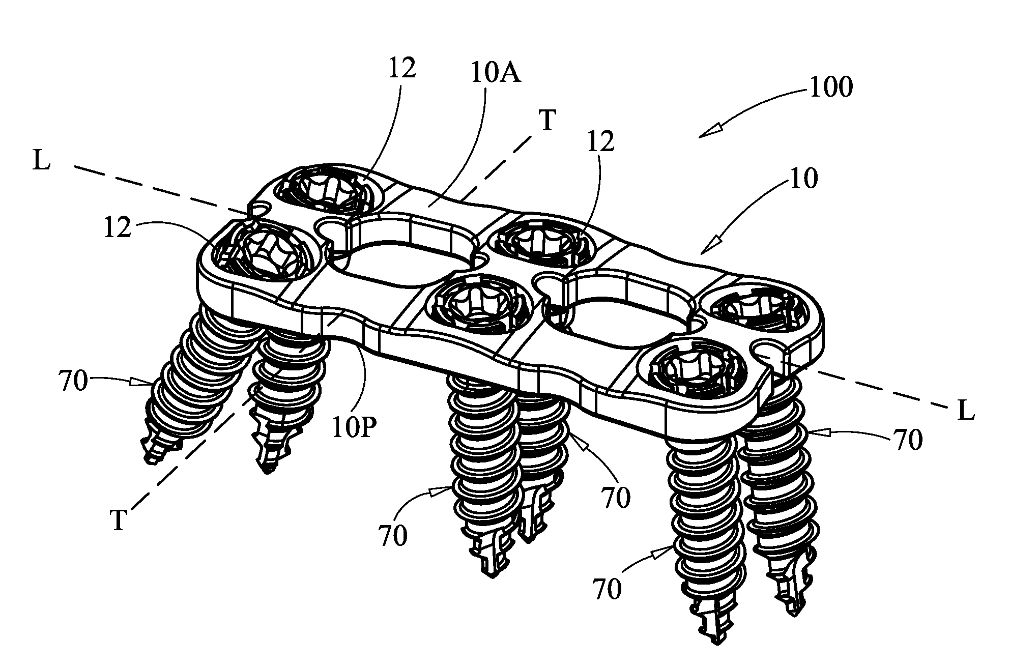
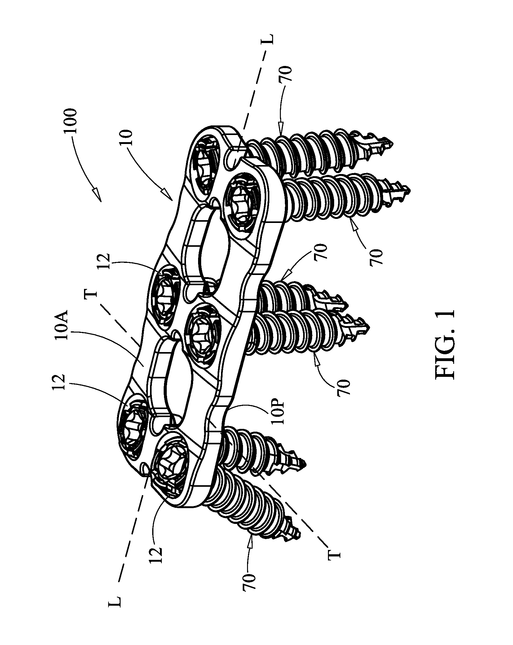
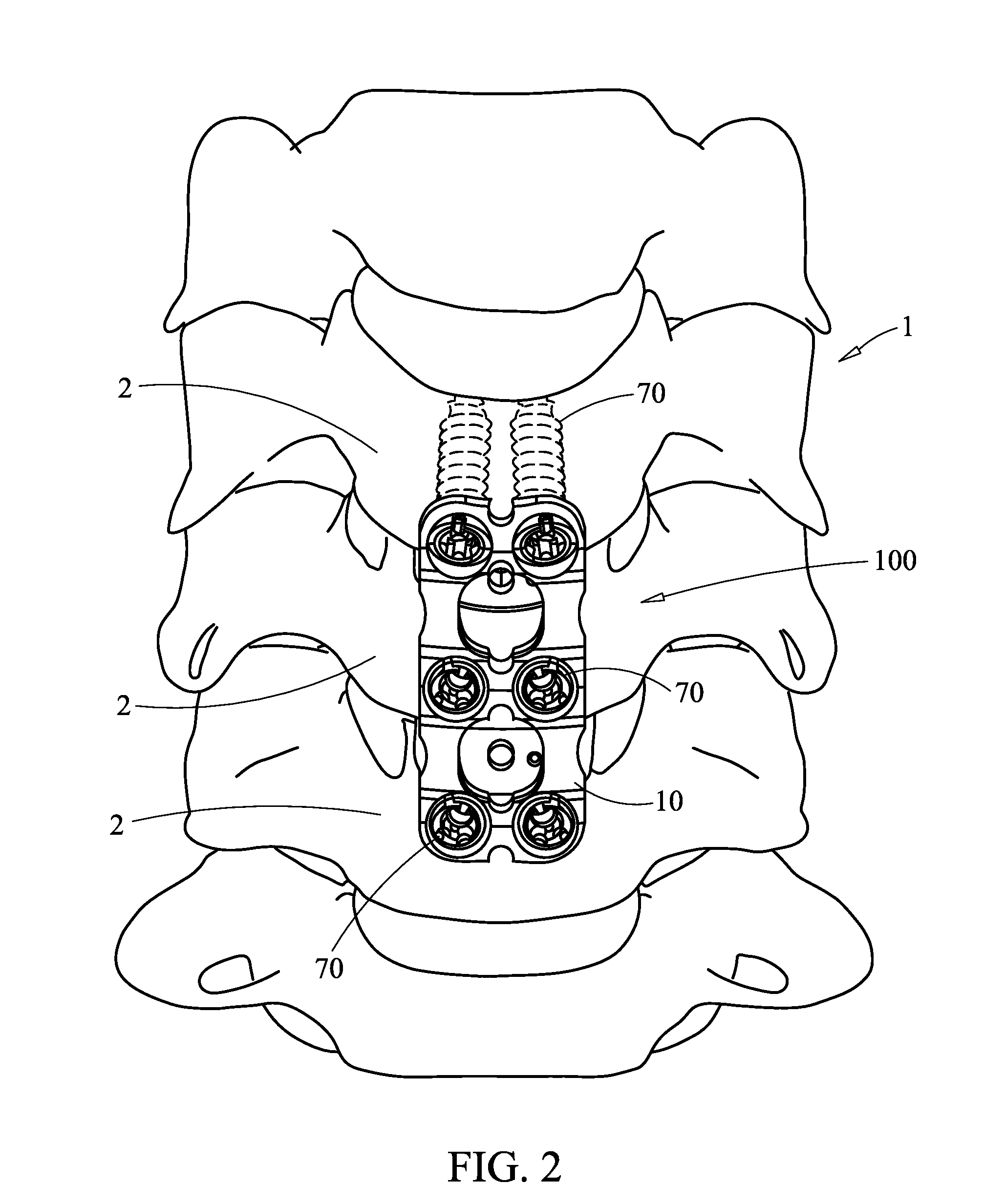
[0005]In one aspect of the present invention, a surgical plate system is provided that includes: a plate having an anterior surface, a posterior surface, a longitudinal axis, a transverse axis and a through hole passing through the anterior and posterior surfaces; and a variable fastener configured and dimensioned to connect to the plate, the variable fastener comprising a head and a shaft extending distally from the head, wherein the head is configured to assume different proximal end diameters, and wherein the head, in a first configuration allows inward flexing to reduce a diameter of the head to allow the head to pass through an entrance opening of the through hole, and wherein in a second configuration, the head is prevented from flexing inwardly thereby preventing the head from backing out of the entrance opening, while allowing articulation of the head, within the through hole, relative to the plate.
[0006]In at least one embodiment, the plate comprises a fixed fastener configured and dimensioned to connect to the plate, the fixed fastener comprising a second head and a second shaft extending distally from the second head, wherein the second head is configured to assume different proximal end diameters, and wherein the second head, in a first configuration allows inward flexing to reduce a diameter of the second head to allow the second head to pass through the entrance opening of the through hole, and wherein in a second configuration, the second head is flexed outwardly, thereby preventing the second head from backing out of the entrance opening and also compressing the second head against inner side walls of the plate surrounding the opening, thereby preventing articulation of the second head, within the through hole, relative to the plate.

Problems solved by technology

In such causes, pain typically results from compression or irritation of spinal nerve roots by reduced spacing between adjacent vertebrae, a damaged disk and / or misalignment of the spine resulting from the injury or degeneration.
Inadequate grafting techniques, poor graft quality and or poor bone quality (e.g., osteoporosis) are factors that can further exacerbate the amount of subsidence that occurs.
Current plate systems do not provide a screw-plate interface that is adequate to account for the subsidence that occurs.
Specifically, current systems do not allow sufficient angulation of the screws relative to the plane of the plate to allow the screws to be oriented as needed during the initial anchoring of the plate to the vertebrae.
Further, many current systems do not allow angular movement of the screws relative to the longitudinal axis of the plate to further accommodate subsidence.

Method used


Image

  • Surgical plate system and method
  • Surgical plate system and method
  • Surgical plate system and method

Examples


Embodiment Construction

[0051]Before the present systems, components and methods are described, it is to be understood that this invention is not limited to particular embodiments described, as such may, of course, vary. It is also to be understood that the terminology used herein is for the purpose of describing particular embodiments only, and is not intended to be limiting, since the scope of the present invention will be limited only by the appended claims.

[0052]Where a range of values is provided, it is understood that each intervening value, to the tenth of the unit of the lower limit unless the context clearly dictates otherwise, between the upper and lower limits of that range is also specifically disclosed. Each smaller range between any stated value or intervening value in a stated range and any other stated or intervening value in that stated range is encompassed within the invention. The upper and lower limits of these smaller ranges may independently be included or excluded in the range, and e...


PUM


Abstract

A surgical plate system, components and methods of using are described. A surgical plate system includes a plate having an anterior surface, a posterior surface, a longitudinal axis, a transverse axis and a through hole passing through the anterior and posterior surfaces. A variable fastener is configured and dimensioned to connect to the plate, the variable fastener having a head and a shaft extending distally from the head. The head is configured to assume different proximal end diameters. The head, in a first configuration allows inward flexing to reduce a diameter of the head to allow the head to pass through an entrance opening of the through hole. In a second configuration, the head is prevented from flexing inwardly thereby preventing the head from backing out of the entrance opening, while allowing articulation of the head, within the through hole, relative to the plate.

Description

BACKGROUND OF THE INVENTION[0001]Back pain can be caused by a variety of factors, including, but not limited to the rupture or degeneration of one or more intervertebral discs due to degenerative disk disease, spondylolisthesis, deformative disorders, trauma, tumors and the like. In such causes, pain typically results from compression or irritation of spinal nerve roots by reduced spacing between adjacent vertebrae, a damaged disk and / or misalignment of the spine resulting from the injury or degeneration.[0002]Common forms of treating such pain include various types of surgical procedures that include mounting a plate across two or more adjacent vertebrae to stabilize them, including, but not limited to aligning the vertebrae to alleviate pain and achieve bony fusion between the aligned vertebrae. After installation of such a plate, once the patient has recovered to the extent where the patient can at least sit upright, the gravitational forces on the spine typically cause some subs...

Claims


Application Information

Patent Timeline
IPC IPC(8): A61B17/88A61B17/56A61B17/80
CPCA61B17/7059A61B17/8038A61B17/8877A61B17/8605A61B17/8685A61B17/8052A61B17/888
Inventor MEKHAIL, ANISMATHER, STEVEN E.GUFFROY, THIBAUTASAAD, WAGDY W.
Owner SPINECRAFT
Why Eureka
Eureka Blog
Learn More