Wrapping machine and wrapping methods

a wrapping machine and wrapping technology, applied in the field of wrapping machines, can solve the problems of reducing the rotation speed of the rotating ring, reducing the productivity of the wrapping machine, and generating considerable forces of inertia during operation, so as to prevent tears and breakages

Active Publication Date: 2012-07-19
AETNA GROUP
View PDF4 Cites 8 Cited by
  • Summary
  • Abstract
  • Description
  • Claims
  • Application Information

AI Technical Summary

Benefits of technology

[0040]A further object of the invention is to make a wrapping machine that is able to operate at high rotation speeds of the rotating ring so as to increase productivity compared with known machines.
[0055]The method further provides a calibrating phase with which to determine, for each new reel of film, an operating difference between the speeds of the rollers to be adopted during operation of the machine, i.e. the prestretching force to which to subject the film for better use thereof and to prevent tears and breakages thereof at the same time.

Problems solved by technology

For example, a relatively fragile single product has to be wound with sufficient tension to maintain the film adhering to the product but not with such as to deform or break the latter.
A drawback of the aforesaid machines is the considerable weight of the rotating ring that during operation generates considerable forces of inertia that are mainly due to the weight of the electric motor, of the counterweights, of the dandy roll and, where present, of the alternator and of the batteries.
This greatly reduces the rotation speed of the rotating ring and consequently limits the productivity of the wrapping machine.
Further, to counteract these inertia forces it is necessary to stiffen significantly the supporting structure and the frame, with a consequent further increase in weight and costs.
A further drawback relates to the creeping contacts used to supply the electric motor, which on the one hand are subject to serious wear and thus have to be replaced frequently and on the other hand further limit the rotation speed of the rotating ring and therefore the productivity of the wrapping machine.
These contacts may further cause sparks and prevent the wrapping machine being installed in environments having a high level of humidity.
Further, where batteries are used, the latter, in addition to being costly, have to be recharged during machine downtime.
If an alternator is used, this causes an increase in the weight to be rotated and further generates current only after the rotating ring starts to rotate, which does not enable the film to be prestretched in an initial wrapping phase.
A further drawback of these machines lies in the operations that are necessary for varying the transmission ratio between the prestretching rollers to vary the prestretching or elongation of the film when it is desired to use different film made of synthetic plastic material, or when it is desired to wrap products of different types, for example groups of stacked products.
These operations, which comprise stopping the wrapping machine, dismantling the transmission unit and refitting a new transmission unit, are extremely slow and laborious and require specialized labor for the performance thereof.
For this reason, the known wrapping machines do not enable the film of synthetic plastic material of each reel to be used in an optimal manner, adjusting suitably the prestretching force in function of the physical and mechanical features of the film of the reel in use.
Still another drawback of the aforesaid wrapping machines consists of the difficulty of maintaining constant the tension of the film wound around the product, especially if the latter has a complex profile or shape, for example an elongated shape, and / or the machine has a rotating ring with high rotation speeds.
This causes a delay in the dispatch of the electric control signal to the motor, a delay that is greater the greater the rotation speed of the rotating ring and / or the dimensions and the shape of the product to be wound.
This delay in the feedback of the prestretching rollers may cause excessive tensioning of the film in non-desired portions of the product to be wound and may lead to the breaking of the film.

Method used


Image

  • Wrapping machine and wrapping methods
  • Wrapping machine and wrapping methods
  • Wrapping machine and wrapping methods

Examples


Embodiment Construction

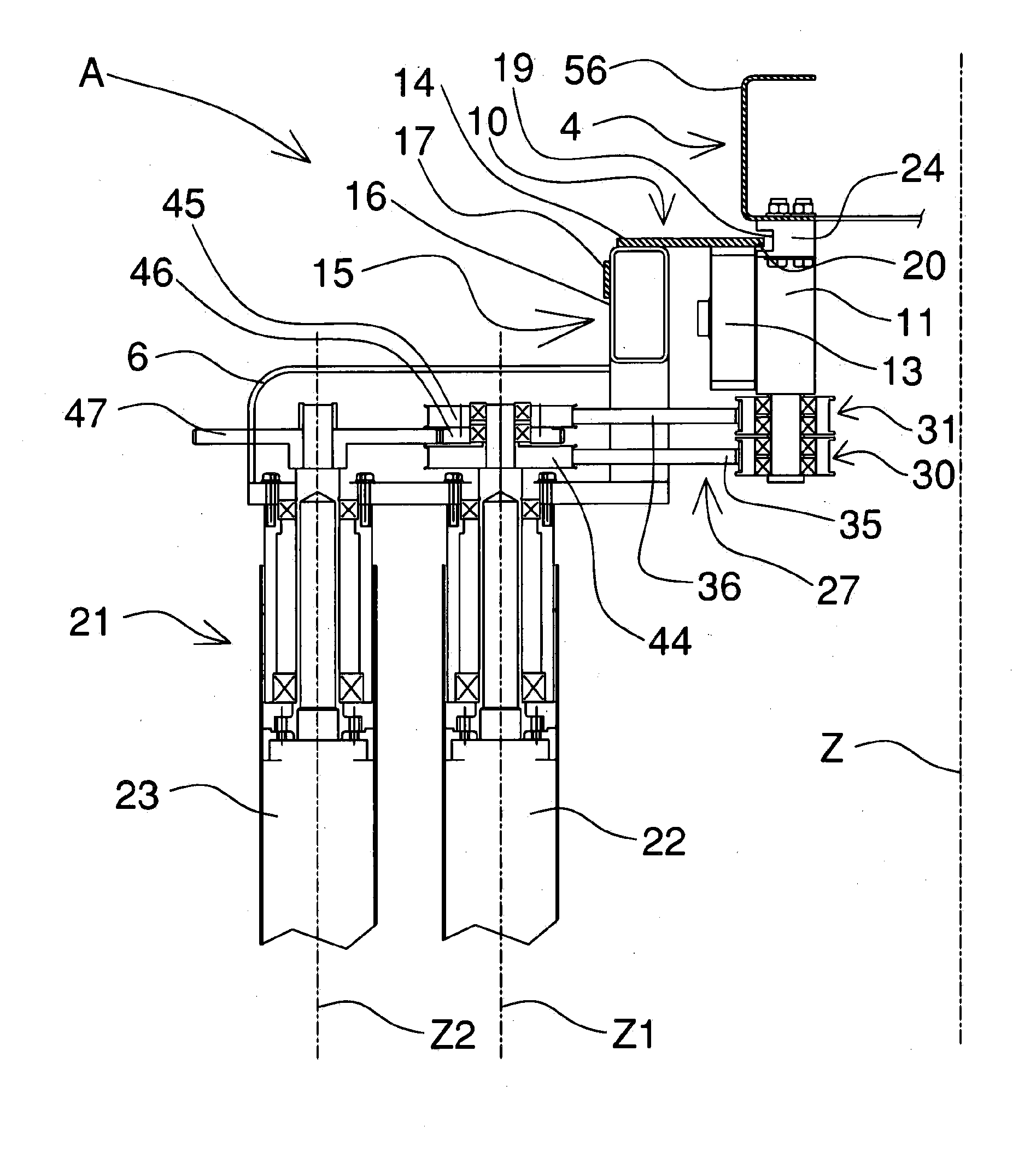
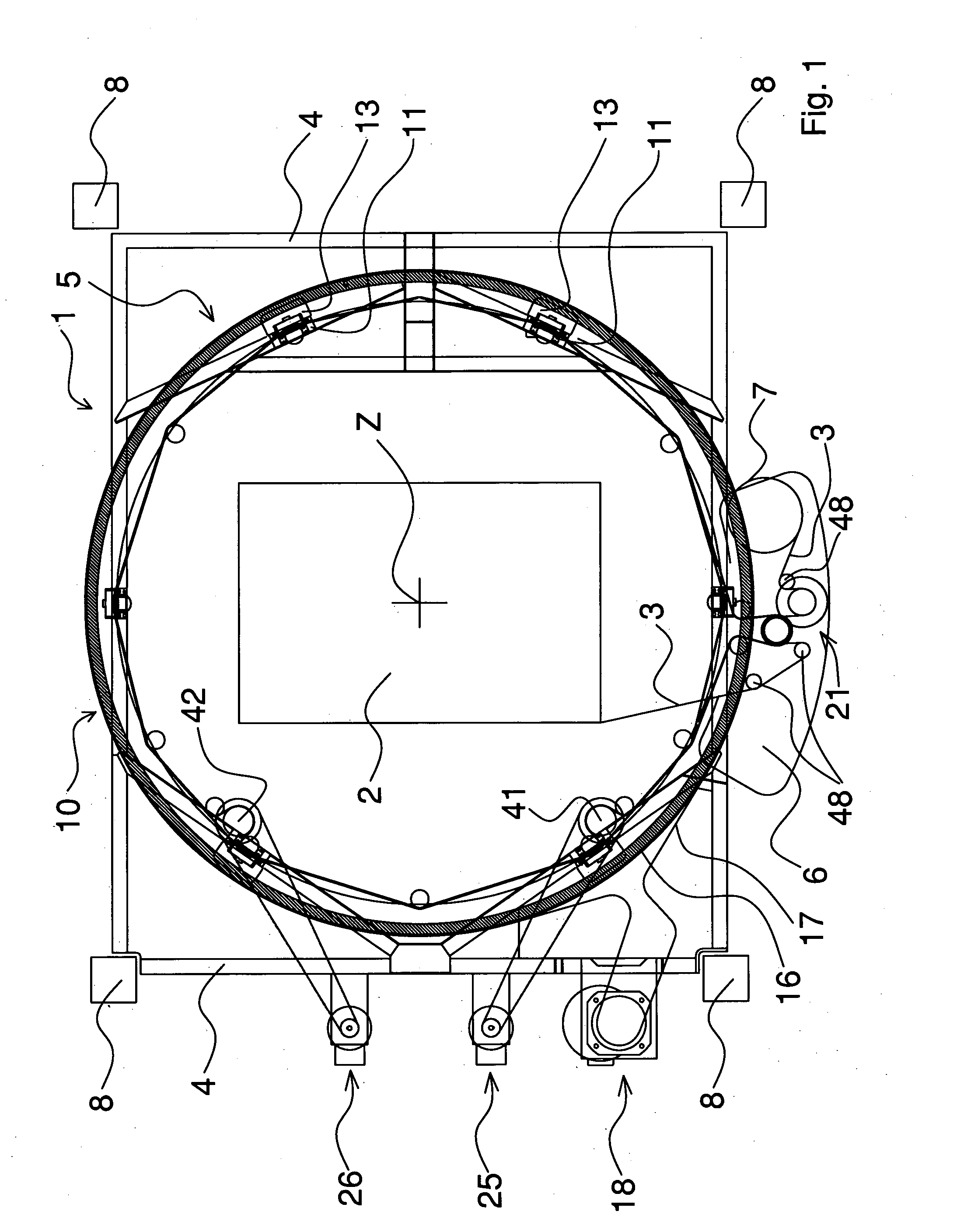
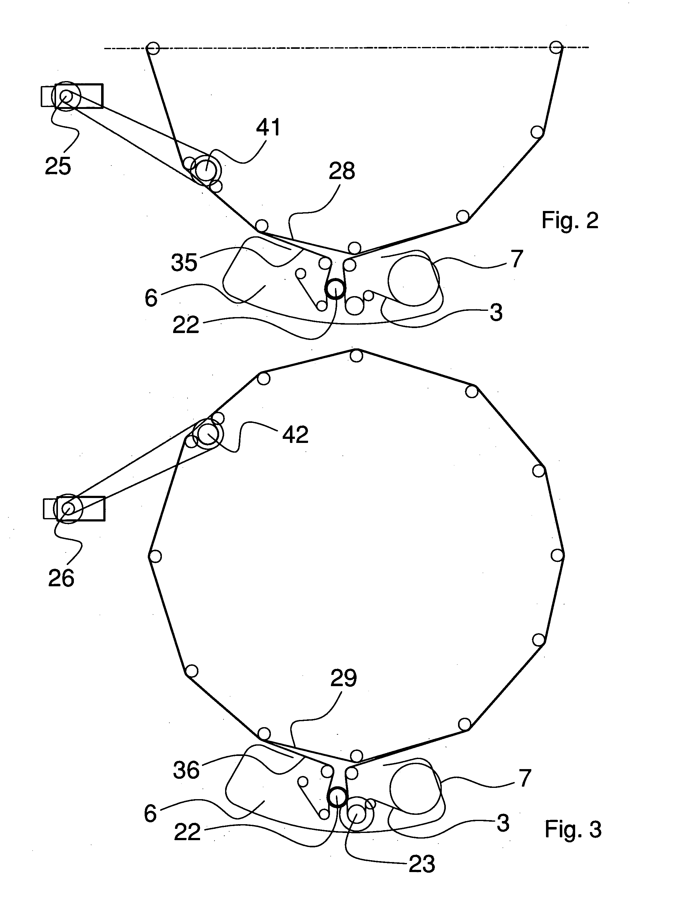
[0069]With reference to FIGS. 1 to 6b, a wrapping machine 1 is shown that is arranged for wrapping a product 2 with a plastic film 3, for example a film of extendible synthetic plastic material wound on a reel 7.

[0070]The wrapping machine 1 comprises a frame 4 supporting a supporting structure 5 of a carriage 6.

[0071]The frame 4, for example bridge-shaped, is associated with a plurality of uprights 8, for example four of them, substantially vertical.

[0072]The uprights 8 are fixable to a floor at a zone in which it is desired to wrap products 2 that are transported there by a conveying device that is not shown, for example comprising a conveyor belt that is slidable below the frame 4.

[0073]Each upright 8 acts as a supporting guide for a carriage, which is not shown, that is associated with the frame 4 and is slidable along an axis that is substantially vertical and substantially parallel to the wrapping axis Z.

[0074]In this way, in use, the carriages move the frame 4 along the wrappi...


PUM

PropertyMeasurementUnit
tensionaaaaaaaaaa
rotation speedaaaaaaaaaa
resisting torqueaaaaaaaaaa

Abstract

A wrapping machine for wrapping a product with a plastic film including a supporting frame with which a ring arrangement is associated that rotates around a wrapping axis of the film and around the product. The supporting frame further supports a carriage arranged for supporting a reel of the film and for supporting a first roller and a second roller for unwinding and stretching the film. A first motor and a second motor are mounted on the supporting frame and coupled, respectively, with the first roller and the second roller.

Description

[0001]This application is a continuation of U.S. Application No. 13 / 192,009 filed Jul. 27, 2011 which is a division of U.S. application Ser. No. 12 / 307,698 filed Feb. 18, 2009. U.S. application Ser. No. 12 / 307,698 is a §371 National Stage entry of PCT International Application No. PCT / IB2007 / 001854 filed Jul. 5, 2007. PCT / IB2007 / 001854 claims priority to IT Application No. MO2006A000221 filed Jul. 7, 2006. The entire contents of these applications are incorporated herein by reference.BACKGROUND OF THE INVENTION[0002]The invention relates to a wrapping machine for wrapping a product with a stretch plastic film and wrapping methods for wrapping the film on the product.[0003]Wrapping machines are known comprising a supporting frame, a supporting structure and a reel-holding carriage.[0004]The supporting frame, which is bridge-shaped, is arranged for supporting the supporting structure and is positioned at a zone in which it is desired to wrap the products, conveyed thereto, for example...

Claims


Application Information

Patent Timeline
Patent Type & Authority Applications(United States)
IPC IPC(8): B65B11/00
CPCB65B11/025B65B2210/18B65B2011/002B65B11/585
Inventor CERE, MAURO
Owner AETNA GROUP
Why Eureka
Try Eureka