System for providing a rapidly elevated aerostat platform

a technology of aerostats and platforms, applied in the field of aerostat systems and methods, can solve the problems that the aerostat that is required to lift the payload may need to be of significant size, and achieve the effect of improving the mobility of the system

Inactive Publication Date: 2012-07-19
INFORMATION SYST LAB
View PDF11 Cites 29 Cited by
  • Summary
  • Abstract
  • Description
  • Claims
  • Application Information

AI Technical Summary

Benefits of technology

[0008]A source of a lighter-than air gas (e.g. Helium) is carried on the base unit and is connected in fluid communication with the aerostat. Additionally, an inflator is mounted on the base unit and is connected in fluid communication with the source of lighter-than-air gas. With this connection, the inflator is used to control the transfer of the lighter-than-air gas to the aerostat during an inflation of the aerostat. The consequence here is that the deployment of the aerostat from the container can be controlled as the aerostat is being inflated.
[0009]As the aerostat is being inflated and deployed from the envelope container, a tether that is affixed to the aerostat is also deployed. More specifically, a tether control unit is mounted on the base unit and it is connected to the tether. Thus, a connection between the aerostat and the base unit is maintained during operation of the aerostat. Specifically, this connection is maintained during a deployment, an in-flight use, and a recovery of the aerostat. In detail, the tether control unit comprises a spool for storing the tether and a winch that will move the spool to establish an operational tension on the tether while the tether is operationally deployed. Further, the system comprises a deployment computer for coordinating respective operations of the inflator, the rotation head, and the tether control unit. For system flexibility, and as a safety measure, the deployment computer is subject to a manu...

Problems solved by technology

Depending on the size and weight of the required payload, however, the ae...

Method used


Image

  • System for providing a rapidly elevated aerostat platform
  • System for providing a rapidly elevated aerostat platform

Examples


Embodiment Construction

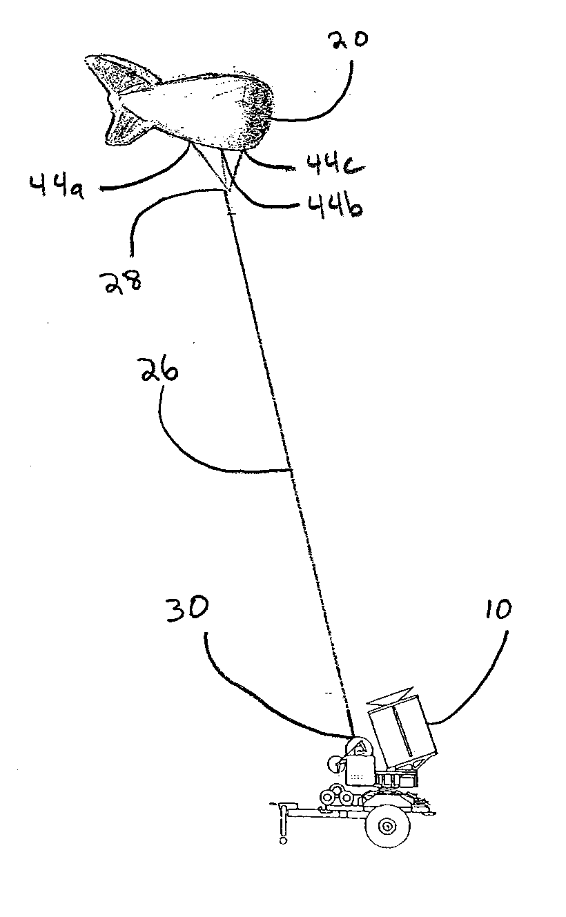
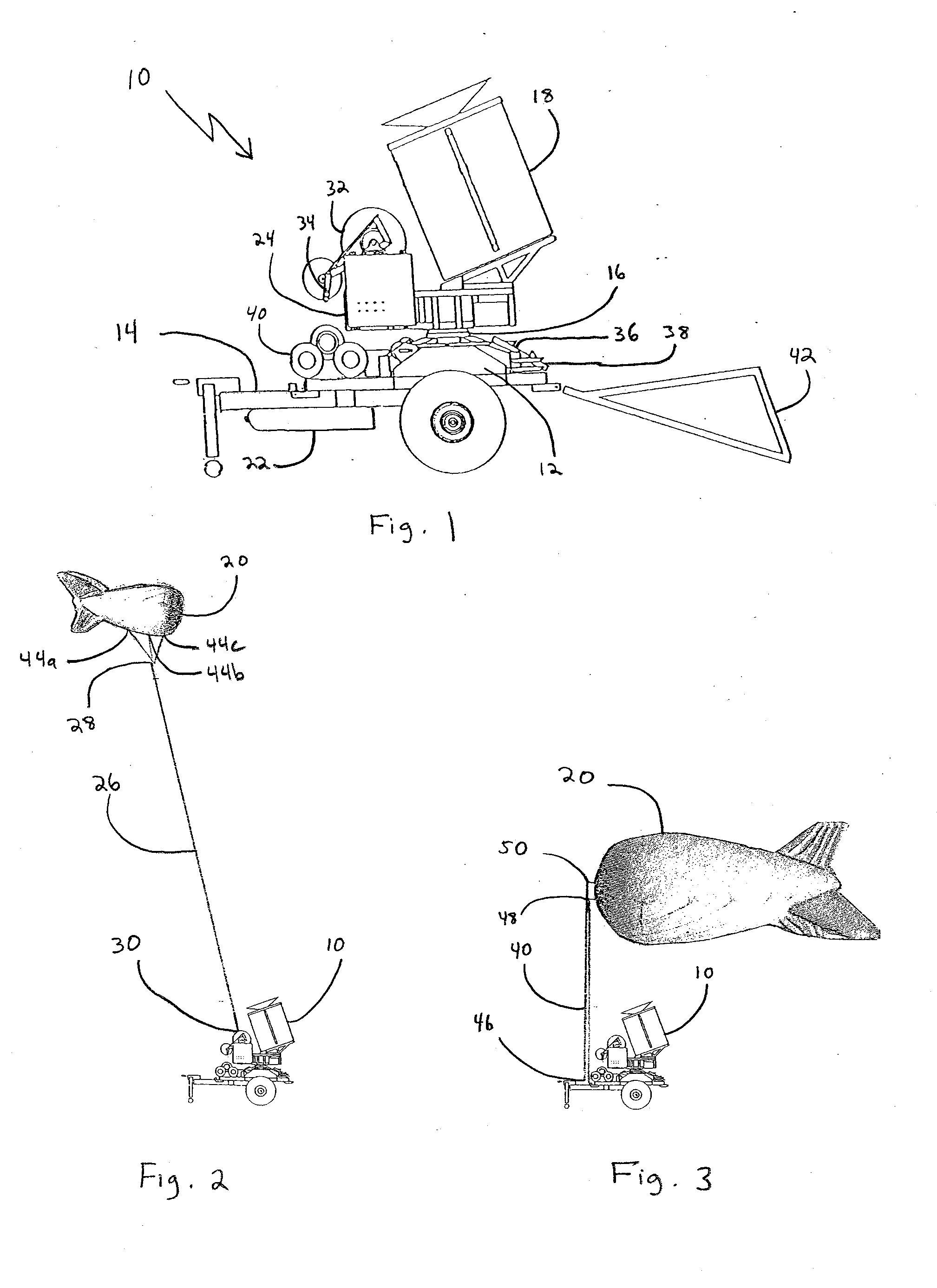
[0016]Referring initially to FIG. 1, a system for providing a rapidly elevated aerostat platform is shown and is generally designated 10. As shown, the system 10 includes a base unit 12 affixed to a transporter 14. In this case, the transporter 14 shown in FIG. 1 is a trailer. As will be appreciated, however, the transporter 14 can also be a wheeled vehicle, a tracked vehicle, or any other form of conveyance known in the art. As shown, a rotation head 16 is attached to the base unit 12. Furthermore, an envelope container 18 for holding a deflated aerostat 20 (See FIG. 2 and FIG. 3) is also mounted on the rotation head 16. In addition to the aforementioned components, a gas source 22 is attached to the underside of the transporter 14 and is connected in fluid communication with the aerostat 20. In the embodiment of the present invention shown in FIG. 1, the gas source 22 is preferably a plurality of Helium-filled tanks. As will be appreciated by the skilled artisan, the gas source 22...


PUM


Abstract

A system and method for deploying a payload with an aerostat uses a mobile transporter for moving the system to a deployment site. Structurally, the system includes a base unit with a rotation head mounted thereon. An envelope container for holding a deflated aerostat is mounted on the rotation head and a rotation of the container on the rotation head positions the aerostat for optimal compliance with the existing wind condition. Also included in the system is an inflator that is mounted on the base unit to inflate the aerostat with a Helium gas. And, the system includes a tether control unit for maintaining a connection with the aerostat during its deployment, in-flight use, and recovery. Preferably, a deployment computer is used for a coordinated control of the rotation head, inflator and tether.

Description

FIELD OF THE INVENTION[0001]The present invention pertains generally to systems and methods for deploying aerostats. More particularly, the present invention pertains to systems and methods for using mobile transporters to selectively position deflated aerostats for rapid operational deployment of the aerostat. The present invention is particularly, but not exclusively, useful as a system and method for use in elevating a substantial payload to a considerable height for operational use at a remote site within a short period of time.BACKGROUND OF THE INVENTION[0002]Surveillance of various types and kinds of activities within an extended area of operation can be extremely helpful in many situations. More specifically, the efficacy of the systems and methods used for this surveillance are enhanced when they are mobile and can be rapidly deployed at selected sites. In addition to the need for effective system functionality, other objectives for the deployment of a mobile system involve ...

Claims


Application Information

Patent Timeline
IPC IPC(8): B64B1/50B64B1/40
CPCB64B1/50B64B1/58B64C2201/022B64F1/14B64C2201/123B64C2201/201B64C2201/208B64C2201/101B64U10/30B64U80/70B64U80/86B64U2101/31B64U2101/30
Inventor VAN STAAGEN, PETER K.MCDANIEL, WILLIAM DOUGLASBOSCHMA, JR., JAMES H.
Owner INFORMATION SYST LAB
Why Eureka
Try Eureka