Programmable Filters for Improving Data Fidelity in Swept-Wavelength Interferometry-Based Systems

a technology of swept-wavelength interferometry and filtering, applied in the field of obtaining the parameter of interest in the swept-wavelength interferometry system, can solve the problems of reducing data fidelity, limiting the utility of the system, and inadequate filters

Active Publication Date: 2012-07-19
BAKER HUGHES INC
View PDF2 Cites 19 Cited by
  • Summary
  • Abstract
  • Description
  • Claims
  • Application Information

AI Technical Summary

Problems solved by technology

However, if the signal frequency is changing, as in swept-wavelength systems, such filters may be inadequate.
The need to design systems to prevent signal aliasing introduces factors that constrain the utility of the system, or can reduce data fidelity.

Method used


Image

  • Programmable Filters for Improving Data Fidelity in Swept-Wavelength Interferometry-Based Systems
  • Programmable Filters for Improving Data Fidelity in Swept-Wavelength Interferometry-Based Systems
  • Programmable Filters for Improving Data Fidelity in Swept-Wavelength Interferometry-Based Systems

Examples


Embodiment Construction

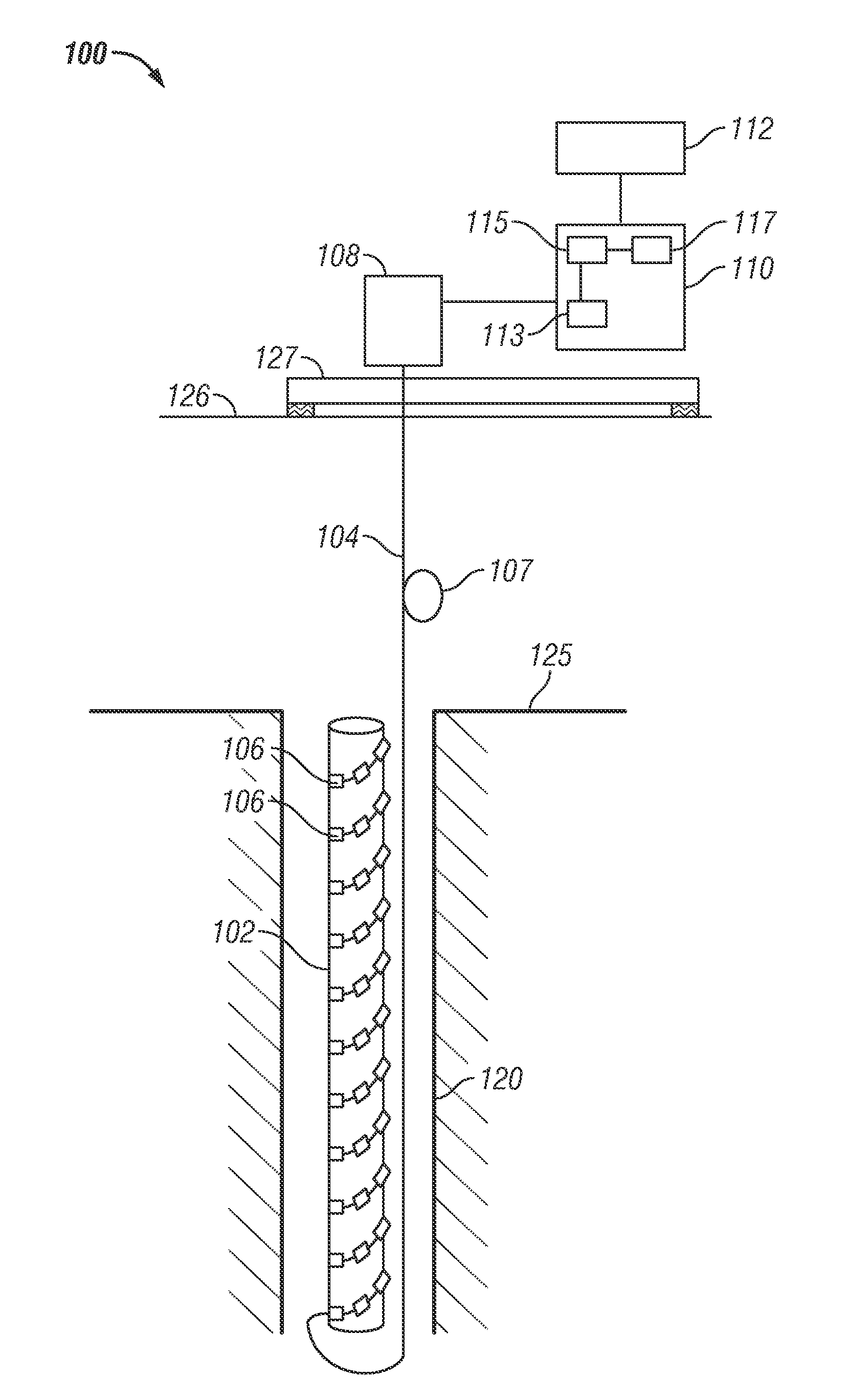
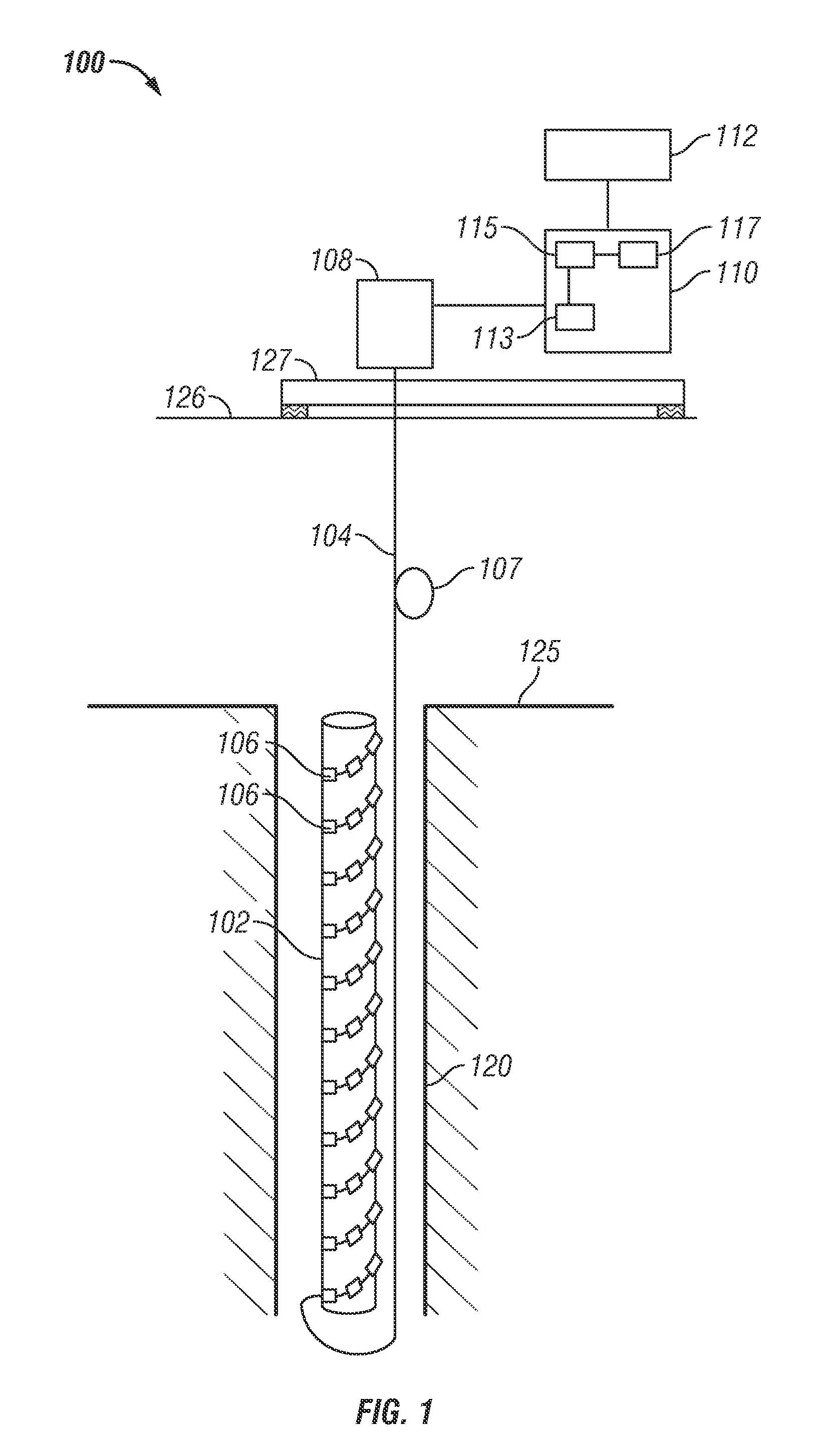
[0012]FIG. 1 shows an exemplary oil production system 100 suitable for use with the exemplary methods and optical system described herein. The exemplary production system 100 of FIG. 1 includes a tubular 102 in wellbore 120 in optical communication with surface electronics via fiber optic cable 104. Fiber optic cable 104 includes a plurality of sensors 106. Each of the plurality of sensors 106 is configured to provide an optical signal upon interaction with a light propagating in the fiber optic cable 104. The fiber optic cable 104 is wrapped around the surface of the tubular 102 and each of the plurality of sensors 106 is thereby attached at a particular location to tubular 102. A change in a parameter, such as strain or temperature, at the particular location is therefore detected by the sensor attached at or near the particular location, which thus provides a signal corresponding to the detected change in parameter. These signals may be processed at surface electronics to obtain ...


PUM


Abstract

A method, system and apparatus for obtaining a parameter of interest from a plurality of sensors in a fiber optic cable deployed in a wellbore are disclosed. Light having variable frequency within a range of frequencies is propagated along the fiber optic cable. Signals are received that are responsive to interaction of the propagated light with the plurality of sensors. The received signals are filtered using a programmable filter. The parameter of interest is obtained from the filtered signals. In one aspect, the fiber optic cable is coupled to a member deployed in the wellbore and the parameter of interest is related to the member.

Description

BACKGROUND OF THE DISCLOSURE[0001]1. Field of the Disclosure The present disclosure relates to obtaining a parameter of interest in a swept-wavelength interferometry systems for use in wellbores.[0002]2. Description of the Related Art[0003]In various aspects of oil exploration and production, optical sensors are deployed downhole and a light source at a surface location supplies light to the optical sensors over a fiber optic cable. Light interacts with the optical sensors to produce a reflected light having a signal that is returned to the surface to be measured. Typically, the returned light is sampled at a sampling device which is controlled using a trigger signal obtained from a suitable source, such as the light source. When sampling signals, a sampling frequency is generally selected that prevents false reconstruction of the original signal, a process known as aliasing. The highest signal frequency that can be successfully reconstructed for a selected sampling frequency is kno...

Claims


Application Information

Patent Timeline
Patent Type & Authority Applications(United States)
IPC IPC(8): G01V5/08
CPCG01V8/20G01V8/005G01V8/24E21B47/00G01V8/16
Inventor DUNCAN, ROGER GLENCHILDERS, BROOKS A.
Owner BAKER HUGHES INC
Why Eureka
Try Eureka