

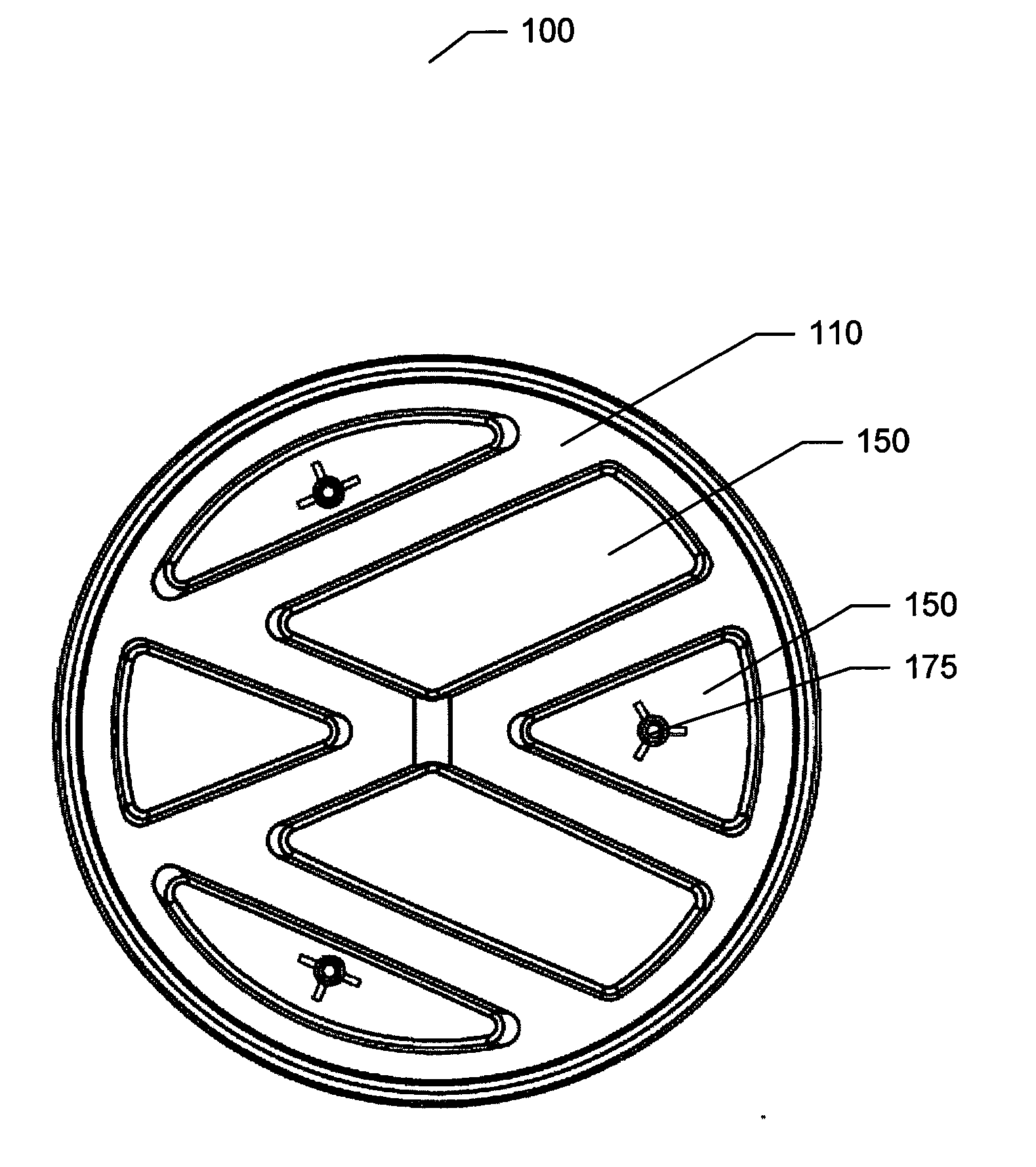
Illuminated vehicle emblem
a vehicle emblem and illumination technology, applied in the field of emblems, can solve the problems of reducing the usefulness of the emblem and expensive automobile repair charges, and achieve the effect of reducing the power drain on the vehicle battery
- Summary
- Abstract
- Description
- Claims
- Application Information
AI Technical Summary
Benefits of technology
Problems solved by technology
Method used
Image

Examples
Embodiment Construction
[0032]Reference will now be made in detail to the preferred embodiments of the present invention, examples of which are illustrated in the accompanying drawings. Wherever possible, the same reference numbers are used in the drawings and the description to refer to the same or like parts.
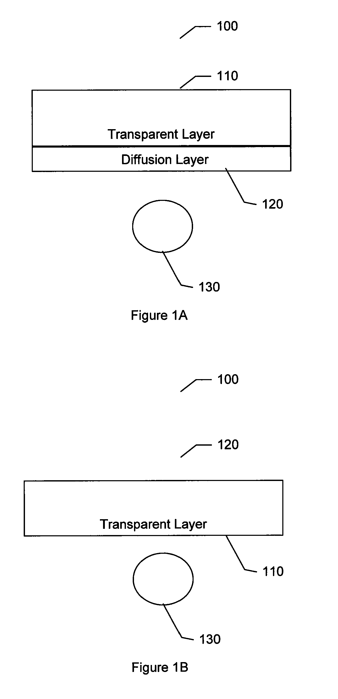
[0033]Refer to FIGS. 1A-1B, which are drawings illustrating side views of an illuminated emblem according to embodiments of the present invention.
[0034]As shown in FIGS. 1A and 1B the illuminated emblem 100 comprises a transparent layer of material 110, a diffusion layer 120, and a light emitting diode 130. In the embodiment illustrated in FIG. 1A the diffusion layer 120 is on the underside or below the transparent layer 110. The LED light source 130 when illuminated or turned on shines light through the diffusion layer 120 and the transparent layer 110. The diffusion layer 120 diffuses the light so that the light exiting the transparent layer 110 is more uniform in brightness. Without a diffusion la...
PUM
 Abstract
Description
Claims
Application Information