Objective lens, optical head, optical disk apparatus, and information processing apparatus

Inactive Publication Date: 2012-07-19
PANASONIC CORP
View PDF12 Cites 1 Cited by
  • Summary
  • Abstract
  • Description
  • Claims
  • Application Information

AI Technical Summary

Benefits of technology

[0025]With the foregoing in view, it is an object of the present invention to provide an objective lens, an optical head, an optical disk apparatus and an information processing apparatus which can suppress deterioration of a focal spot caused by a drop in diffraction efficiency.
[0028]According to the present invention, the diffraction efficiency of the laser beam having the wavelength λ2, which is diffracted by the second area and converges on the information recording surface of the second information recording medium, is greater than the diffraction efficiency of the laser beam having the wavelength λ1 which is diffracted by the second area and converges on the information recording surface of the first information recording medium, hence when information is recorded or reproduced on or from the second information recording medium, the intensity of the laser beam, which decreases as the distance from the optical axis increases, can be corrected by increasing the diffraction efficiency of the laser beam having the wavelength λ2 which enters the objective lens in an area near the edge of the objective lens, whereby the deterioration of the focal spot caused by a drop in the diffraction efficiency can be suppressed.

Problems solved by technology

As a result, the focal spot on the information recording surface of the optical disk cannot be sufficiently focused.
If diffraction efficiency of the laser beam which enters the objective lens becomes completely zero in a part of the area like this, deterioration of the focal spot on the information recording surface becomes enormous.
If the intensity of the laser beam which enters the objective lens drops dramatically in the outer circumference, as mentioned above, the focal spot on the information recording surface of the optical disk cannot be sufficiently focused, but this problem of the conventional compatible objective lens is not mentioned in Patent Literature 2.

Method used


Image

  • Objective lens, optical head, optical disk apparatus, and information processing apparatus
  • Objective lens, optical head, optical disk apparatus, and information processing apparatus
  • Objective lens, optical head, optical disk apparatus, and information processing apparatus

Examples


embodiment 1

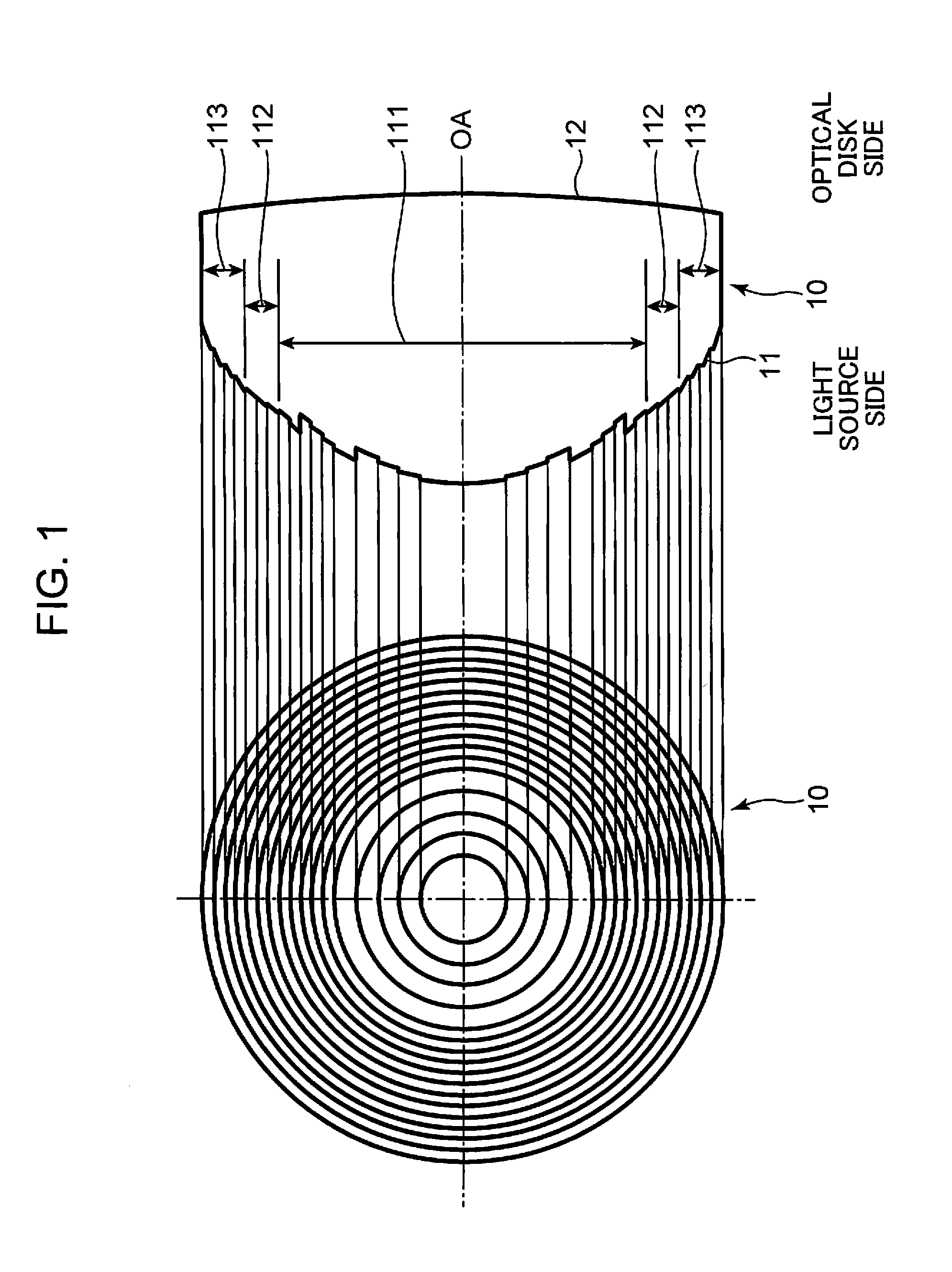
[0053]FIG. 1 is a diagram depicting a configuration of an objective lens according to Embodiment 1 of the present invention. The left drawing in FIG. 1 is a schematic plan view depicting a configuration of an objective lens 10 of Embodiment 1, and the right drawing in FIG. 1 is a schematic cross-sectional view depicting the configuration of the objective lens 10 of Embodiment 1.

[0054]The objective lens 10 of Embodiment 1 is used as a compatible objective lens which can support both the BD for recording or reproducing information using a blue-violet laser beam having a wavelength λ1, and the DVD for recording or reproducing information using a red laser beam having the wavelength λ1 which is longer than the wavelength λ1.

[0055]The objective lens 10 has a spherical surface or an aspherical surface to be a base on an entrance surface 11 on the light source side (side where the laser beam enters). On the spherical surface or the aspherical surface to be a base (hereafter generically cal...

embodiment 2

[0108]FIG. 6 is a diagram depicting a configuration of an objective lens according to Embodiment 2 of the present invention. The left drawing in FIG. 6 is a schematic plan view depicting a configuration of an objective lens 20 of Embodiment 2, and the right drawing in FIG. 6 is a schematic cross-sectional view depicting the configuration of the objective lens 20 of Embodiment 2.

[0109]The objective lens 20 of Embodiment 2 is used as a compatible objective lens which can support both the BD for recording or reproducing information using a blue-violet laser beam having a wavelength λ1, and the DVD for recording or reproducing information using a red laser beam having a wavelength λ2 which is longer than the wavelength λ1.

[0110]The objective lens 20 has a spherical surface or an aspherical surface to be a base on an entrance surface 21 on the light source side (side where the laser beam enters). On the spherical surface or the aspherical surface to be a base (hereafter generically calle...

embodiment 3

[0134]FIG. 7 is a diagram depicting a configuration of an objective lens according to Embodiment 3 of the present invention. The left drawing in FIG. 7 is a schematic plan view depicting a configuration of an objective lens 30 of Embodiment 3, and the right drawing in FIG. 7 is a schematic cross-sectional view depicting the configuration of the objective lens 30 of Embodiment 3.

[0135]The objective lens 30 of Embodiment 3 is used as a compatible objective lens which can support both the BD for recording or reproducing information using a blue-violet laser beam having a wavelength λ1, and the DVD for recording or reproducing information using a red laser beam having a wavelength λ2 which is longer than the wavelength λ1.

[0136]The objective lens 30 has a spherical surface or an aspherical surface to be a base on an entrance surface 31 on the light source side (side where the laser beam enters). On the spherical surface or the aspherical surface to be a base (hereafter generically calle...


PUM


Abstract

An objective lens, an optical head, an optical disk apparatus and an information processing apparatus which can suppress deterioration of a focal spot caused by a drop in the diffraction efficiency are provided. An inner circumference area (111) and an outer circumference area (113) converge a laser beam having an order of diffraction with which diffraction efficiency is highest, out of laser beams having a wavelength λ1 which are diffracted by the inner circumference area (111) and the outer circumference area (113), on an information recording surface of a first information recording medium; the inner circumference area (111) and a mid-circumference area (112) converge a laser beam having an order of diffraction with which diffraction efficiency is highest, out of the laser beams having a wavelength λ2 which are diffracted by the inner circumference area (111) and the mid-circumference area (112), on an information recording surface of a second information recording medium; and the diffraction efficiency of the laser beam having the wavelength λ2, which is diffracted by the mid-circumference area (112) and converges on the information recording surface of the second information recording medium, is greater than the diffraction efficiency of the laser beam having the wavelength λ1 which is diffracted by the mid-circumference area (112), and converges on the information recording surface of the first information recording medium.

Description

TECHNICAL FIELD[0001]The present invention relates to an objective lens for converging laser beams emitted from the laser power supply onto information recording surfaces of a plurality of types of information recording media such as optical disks, to an optical head which is provided with the objective lens and optically records or reproduces information on or from information recording media, to an optical disk apparatus provided with the optical head, and to an information processing apparatus provided with the optical disk apparatus.BACKGROUND ART[0002]As a blue-violet semiconductor laser has been put into practical use, a Blu-ray disc (hereafter BD), as a high-density and large-capacity optical information recording medium (hereinafter, also called as an optical disk) and having substantially the same size as a CD (Compact Disc) and a DVD (Digital Versatile Disc), has been put into practical use. BD is an optical disk for recording or reproducing information on or from an infor...

Claims


Application Information

Patent Timeline
IPC IPC(8): G11B7/1353
CPCG11B7/1353G11B7/1367G02B5/1895G11B7/13922G11B2007/0006G11B7/1374
Inventor YAMASAKI, FUMITOMOMINAMI, KAZUHIROKOMMA, YOSHIAKIASADA, JUNICHIKAJINO, OSAMUTERAHARA, NORIAKITANAKA, TOSHIYASU
Owner PANASONIC CORP
Why Eureka
Try Eureka