Power distribution system

a technology of power distribution system and configuration, applied in the direction of coupling device connection, process and machine control, instruments, etc., can solve the problem that the system does not have a configuration for notifying the user of the change of power source, and achieve the effect of reducing the electricity ra

Inactive Publication Date: 2012-07-19
PANASONIC INTELLECTUAL PROPERTY MANAGEMENT CO LTD
View PDF3 Cites 7 Cited by
  • Summary
  • Abstract
  • Description
  • Claims
  • Application Information

AI Technical Summary

Benefits of technology

[0005]In view of the above, the present invention provides a power distribution system capable of notifying a user of change of power sources such that the user can easily perceive it.
[0008]With this configuration, it is possible to easily notify the user of the change of the power sources, and to motivate the user to save electric power and reduce the electricity rate.
[0012]Accordingly, since the display control is performed based on the uses of the solar battery, the secondary cell and the commercial power source, it is possible to suppress the power consumption of the commercial power source and reduce the electricity rates.
[0014]By this configuration, the modes using the commercial power source, the solar battery and the secondary cell are subdivided and the display control is performed based on the uses of the solar battery, the secondary cell and the commercial power source. Accordingly, it is possible to suppress the power consumption of the commercial power source and reduce the electricity rates.
[0016]Accordingly, it is possible to encourage the user to save electric power and reduce the electricity rate by varying the display depending on different electricity rates during different times of the day.

Problems solved by technology

However, no system has configuration for notifying a user of change of power sources such that the user can easily perceive it.

Method used


Image

  • Power distribution system
  • Power distribution system
  • Power distribution system

Examples


first embodiment

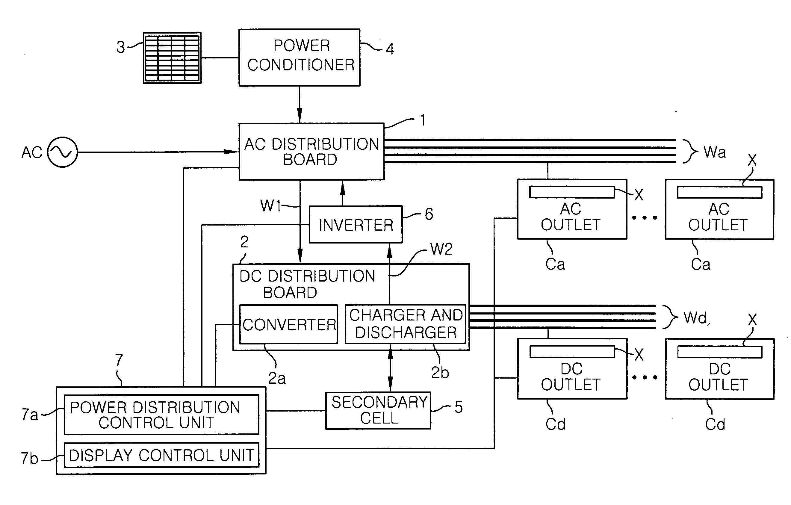
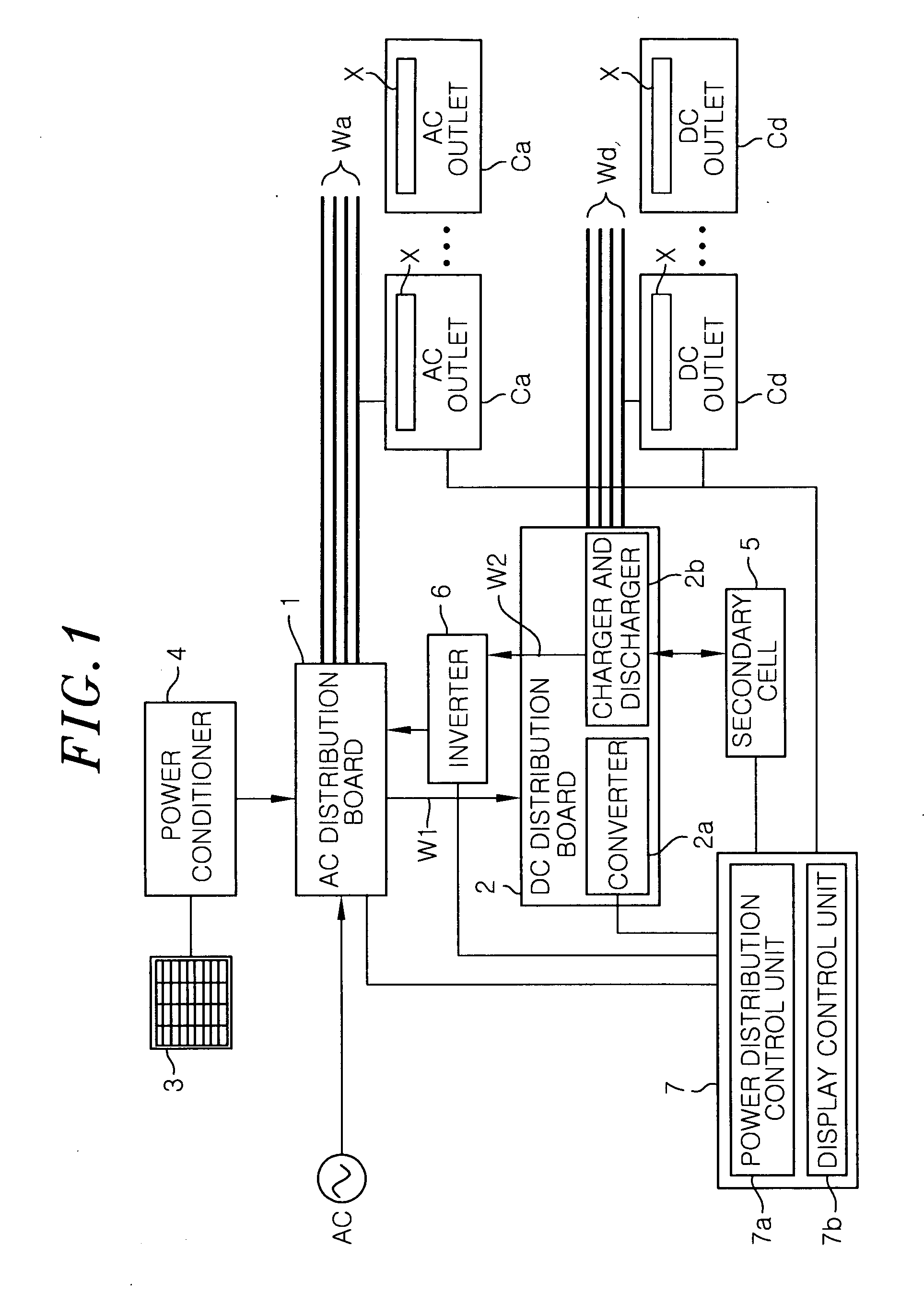
[0024]FIG. 1 shows a power distribution system in accordance with a first embodiment of the present invention which is applied to a house, for example. The power distribution system includes an AC distribution board 1 connected to an AC power feed line Wa having an AC outlet Ca serving as an electric power outlet, which is connected to an AC appliance (not shown), and a DC distribution board 2 connected to a DC power feed line Wd having a DC outlet Cd serving as an electric power outlet, which is connected to a DC appliance (not shown). Further, power sources of the system include a commercial AC power source serving as an AC power source and at least one of a solar battery 3 and a secondary cell 5 serving as a DC power source.

[0025]Hereinafter, the present invention will be described as an example applied to a detached independent house, but it is not limited thereto and it may be applied to an apartment, an office, a factory and the like.

[0026]The AC distribution board 1 connected...

second embodiment

[0069]Although the controller 7 performs a power distribution control for changing the power sources based on the power supply amounts of the respective power sources in the first embodiment, the controller 7 may perform a power distribution control for changing the power sources based on the power demand amount at the side of the outlet C, i.e., loads.

[0070]In this case, the controller 7 determines the power demand amount by monitoring the AC electric power supplied to the AC power feed line Wa from the AC distribution board 1 and the DC electric power supplied to the DC power feed line Wd from the DC distribution board 2, or by acquiring information on the power consumption from the AC outlet Ca and the DC outlet Cd. Further, if the power demand amount is small, the solar battery 3 and / or the secondary cell 5 are / is used as the power sources / source. As the power demand amount increases, the commercial AC power source is used jointly with the solar battery 3 and / or the secondary ce...


PUM


Abstract

A power distribution system includes power sources and an outlet which is supplied with electric power from the power sources and displays information on which power source is currently supplying the electric power. Further, the power distribution system includes a controller which changes the power sources for supplying the electric power to the outlet and controls the display on the outlet.

Description

FIELD OF THE INVENTION [0001]The present invention relates to a power distribution system.BACKGROUND OF THE INVENTION[0002]Alternative current (AC) appliances such as an air conditioner, a refrigerator and a washing machine are supplied with electric power from a commercial power source (AC power source). A direct current (DC) appliance such as a personal computer, a liquid crystal television, a telephone or a facsimile is driven by a DC power source. There are proposed techniques for employing both an AC power distribution system for supplying AC electric power and a DC power distribution system for supplying DC electric power in a house or store. (see, e.g., Japanese Patent Application Publication No. 2009-178025)[0003]In a power distribution system in a house, generally, a commercial power source, a solar battery, a secondary cell charged with surplus electric power or the like is used to supply electric power to the appliances. Further, the system changes the power sources for s...

Claims


Application Information

Patent Timeline
Patent Type & Authority Applications(United States)
IPC IPC(8): G05F5/00
CPCH01R13/6691H02J3/02H02J3/005H01R25/006Y02P80/10H02J3/007Y04S20/00Y02B90/20
Inventor TAKEHARA, KIYOTAKAYANAGI, YASUHIROTAKAMIYA, AKIKO
Owner PANASONIC INTELLECTUAL PROPERTY MANAGEMENT CO LTD
Why Eureka
Try Eureka