Self-organized power and energy control and management systems and methods

a power and energy control and management system technology, applied in the field of self-organized power and energy control and management systems, can solve the problems of increasing complexity and cost of application specific systems, affecting reducing the life of equipment connected, so as to improve data access, storage and updating.

Active Publication Date: 2012-07-19
ROCKWELL AUTOMATION TECH
View PDF3 Cites 3 Cited by
  • Summary
  • Abstract
  • Description
  • Claims
  • Application Information

AI Technical Summary

Benefits of technology

[0009]The present embodiments overcomes the aforementioned drawbacks of the previous strategies by providing systems and methods that are adapted to self-organize a multifunctional power and energy control and management system by integrating multiple backplane based modules through module descriptions without the need for a user to configure the system by inputting system information into configuration software. A dynamic data structure may be configured based on the module descriptions to improve data access, storage and updating.

Problems solved by technology

Often, for power and energy related control and monitoring applications, there are a variety of application specific requirements that add complexity and cost to the application specific systems, typically based on the types and amounts of data gathered.
Using power monitoring as an example, unfavorable events, such as voltage sags, swells, or transient events can occur randomly any location within a facility's distribution system.
These events can damage or reduce the life of equipment connected to the distribution system, they can cause connected equipment to malfunction, or even worse, cause harm to personnel.
For example, when these prior known systems are configured for first time use, or when additional modules are added to the system, these systems are not able to “self organize,” meaning they need user intervention prior to and during initialization and revisions in order to properly configure the system to function according to the desired application.
In addition, prior known systems have not adequately addressed the need for greater data storage while combining greater data storage with improved data access speeds.
If an error in the configuration of the system is made by the user, the system may not recognize the error because the system would be configured based upon the user input.
Additionally, these systems typically access and store large amounts of power and energy related data for later review and analysis.
Because these databases are general purpose, they are rarely if ever suitable for the ever increasing large amounts of power and energy related data that is accessed, stored, and frequently updated.

Method used


Image

  • Self-organized power and energy control and management systems and methods
  • Self-organized power and energy control and management systems and methods
  • Self-organized power and energy control and management systems and methods

Examples


Embodiment Construction

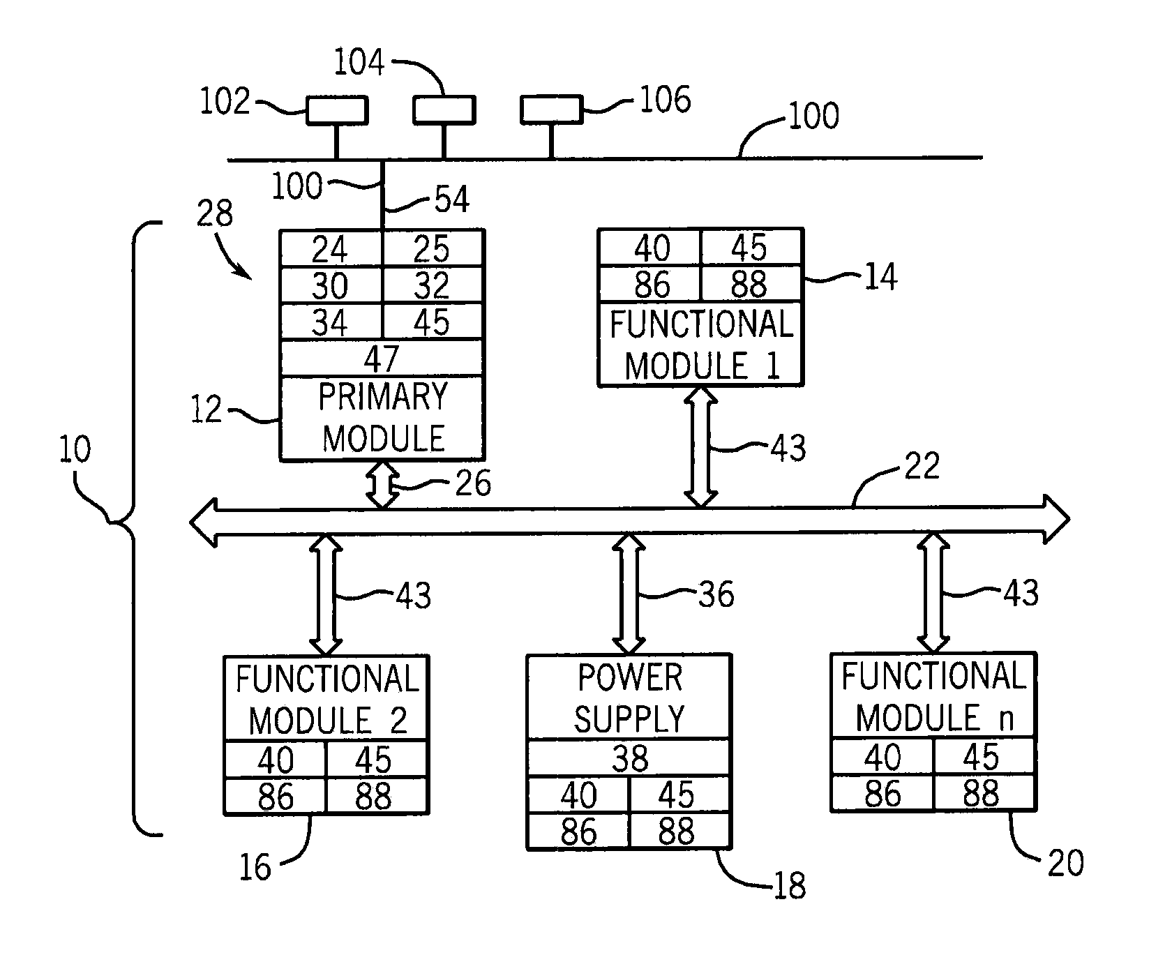
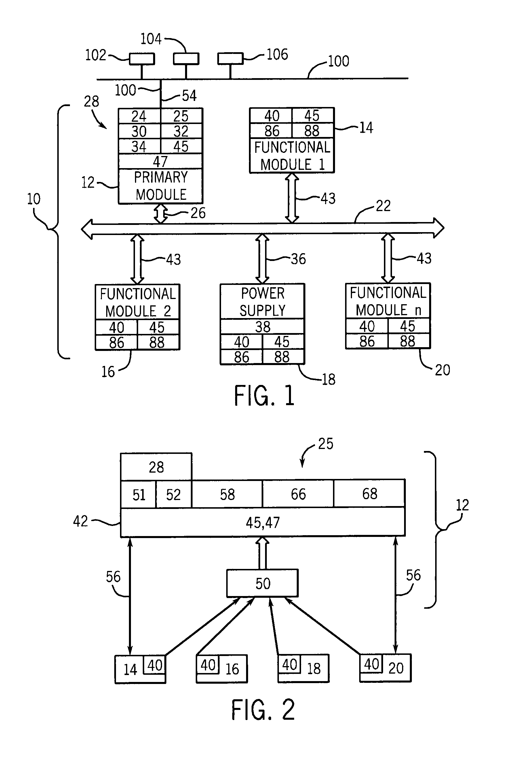
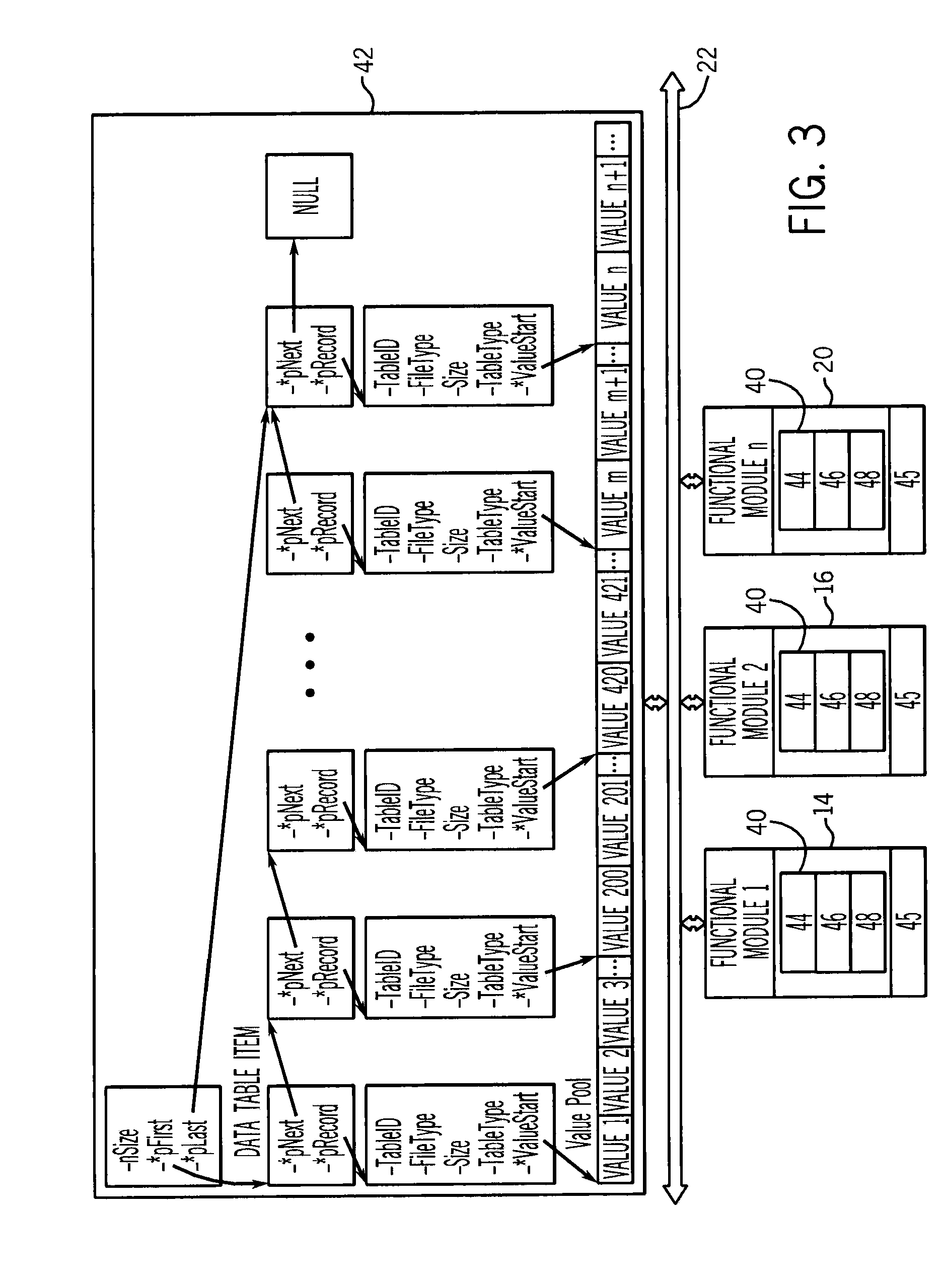
[0022]The various aspects of the present embodiments will be described in connection with various power and energy related control and management systems and methods. That is because the features and advantages that arise due to the embodiments are well suited to this purpose. For this reason, the systems and methods will be described in the context of a system configured for a power monitoring application. Still, it should be appreciated that the various aspects of the invention can be applied to achieve other objectives as well. For example, the systems and methods of the present invention may include systems adapted for other applications such as HVAC, line synchronization, motor protectors, transformer protectors, application specific devices, and any combination, as non-limiting examples, for the same or similar purposes.

[0023]A flexible and multifunctional product platform is disclosed and can be adapted to meet any of the application requirements mentioned herein. This platfo...


PUM


Abstract

Systems and methods self-organize a multifunctional power and energy control and management system by integrating multiple backplane based modules through module descriptions. Dynamic data table structures may be configured based on information provides with the module descriptions and provide for improved data accessing, storing, and updating.

Description

CROSS-REFERENCE TO RELATED APPLICATIONS[0001]Not applicable.STATEMENT REGARDING FEDERALLY SPONSORED RESEARCH OR DEVELOPMENT[0002]Not applicable.BACKGROUND OF THE INVENTION[0003]The present invention relates generally to power and energy related control and monitoring functions and, more particularly, to systems and methods for building a multifunctional power and energy control and management system by integrating multiple backplane based modules through module descriptions.[0004]Often, for power and energy related control and monitoring applications, there are a variety of application specific requirements that add complexity and cost to the application specific systems, typically based on the types and amounts of data gathered. Examples of power and energy related control and monitoring applications include power monitoring, HVAC, line synchronization, motor protectors, transformer protectors, and application specific devices. Using power monitoring as an example, unfavorable even...

Claims


Application Information

Patent Timeline
Patent Type & Authority Applications(United States)
IPC IPC(8): G06F1/26G06F17/30
CPCG05B19/0426G05B2219/25009G05B2219/25066Y04S20/227G05B2219/32144H02J13/0079Y02B70/3241G05B2219/25093H02J13/00002H02J2310/12H02J13/00004Y04S20/00Y02B90/20G06F1/26G06F15/163Y02A30/60Y02B70/30Y04S20/20
Inventor XIAO, XUYUANDELKER, MARK E.TANG, BENFENGCHEN, CHAOLOMBARDI, STEVEN A.BERMAN, DAVID
Owner ROCKWELL AUTOMATION TECH
Why Eureka
Try Eureka