[0010]In view of the above problems, it is an object of the present invention to provide a compact industrial
robot in which a
stroke of a balancer device can be long, and the balancer device can avoid interference with a frame and have a large extent of rotation of an arm while ensuring the strength of the arm.
[0011]According to the present invention, the above object is achieved by providing an industrial
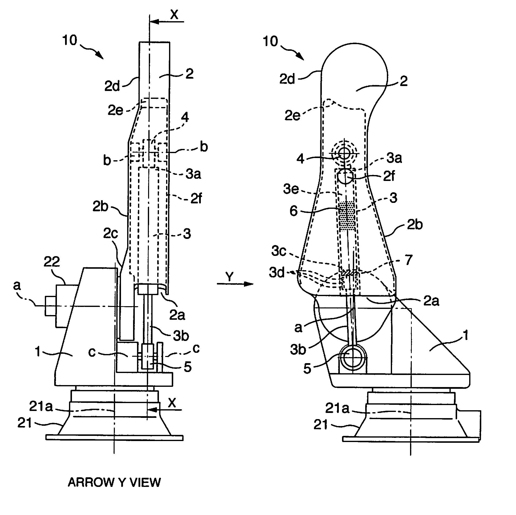
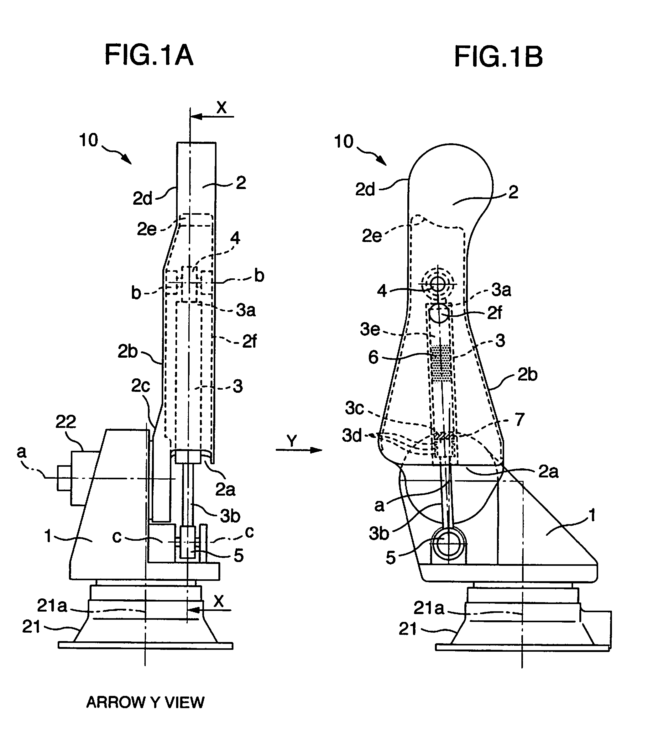
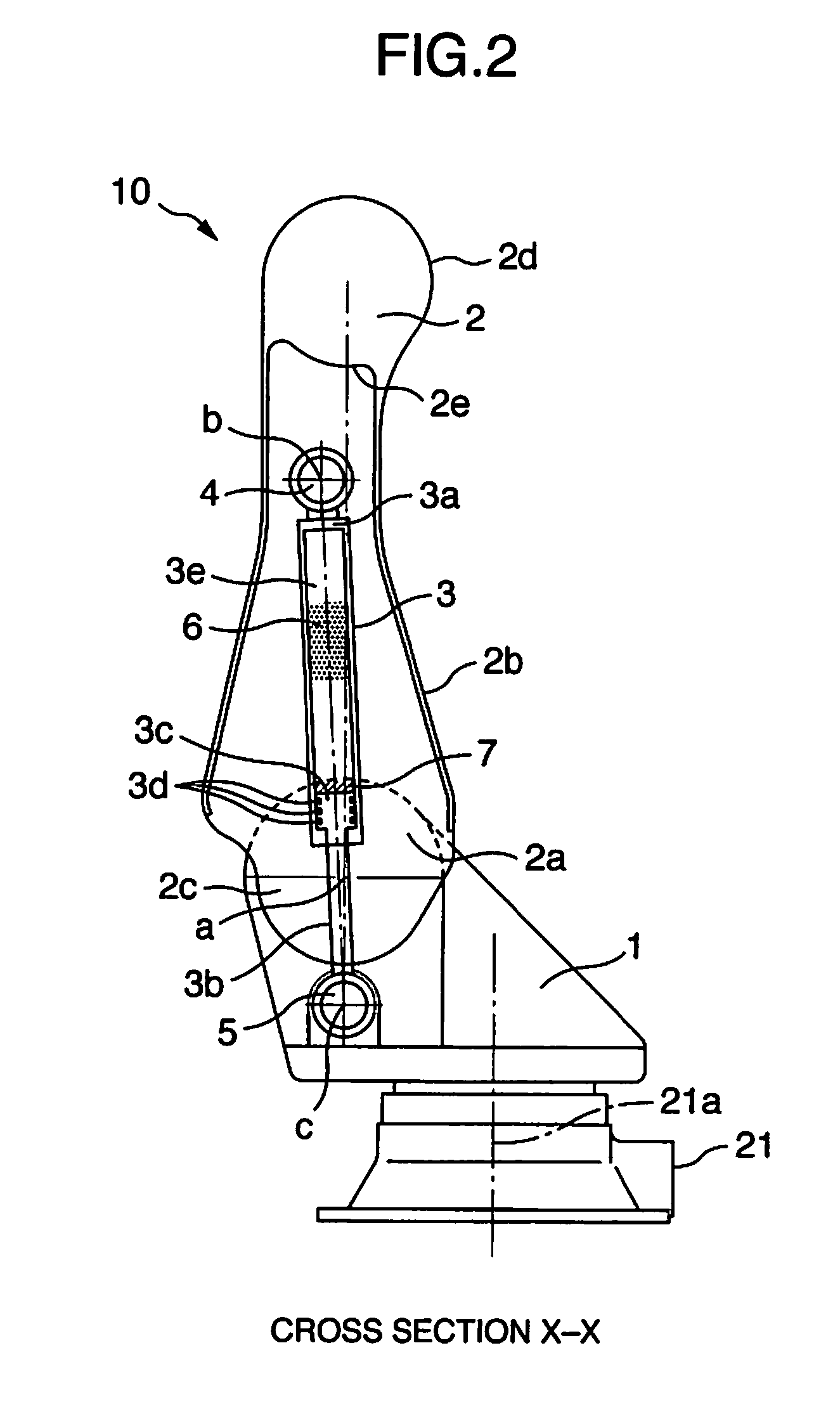
robot including an arm rotatably supported about a horizontal rotation shaft provided on a frame, and a balancer device for reducing a load of the arm, wherein the arm has a proximal portion rotatably supported on the horizontal rotation shaft in a
cantilever state, a cylindrical case portion opened on the proximal portion side and formed from the proximal portion side to a distal end of the arm, and an arm distal end portion, the balancer device has a rod having an engagement portion at a distal end thereof, and a cylinder into and out of which the rod is pulled, the engagement portion at the distal end of the rod is rotatably supported between a pair of first support portions provided on the frame on a lower side of the horizontal rotation shaft, a rear end of the cylinder on an opposite side to the rod is rotatably supported between a pair of second support portions provided inside the cylindrical case portion, and the cylindrical case portion and the balancer device are arranged so as not to interfere with each other in an extent of rotation of the arm, including both sides of the horizontal rotation shaft.
[0014]Further, in an invention according to claim 4, a rotation center of the first support portions, the horizontal rotation shaft, a rotation center of the second support portions, and a
gravity center of the arm are in such a relationship as to be aligned along a straight line when the arm is at an upright position. Accordingly, the length of the balancer device becomes maximum when a load of the arm is small, so that the length of the balancer device becomes short to increase the reaction force as the load increases by the rotation of the arm.
[0015]The industrial robot of the invention can ensure a long
stroke of the balancer device, avoid interference between the arm and the frame, and increase an extent of rotation of the arm while ensuring the strength of the arm, by making the arm in a
cantilever state, providing the cylindrical case portion opened on the proximal portion side and formed toward the distal end of the arm between both ends of the arm, rotatably supporting the balancer device on the cylinder side between the second support portions inside the cylindrical case portion, rotatably supporting the engagement portion of the balancer device at the distal end of the rod between the first support portions on the frame on the lower side of the horizontal rotation shaft, so that the cylindrical case portion and the balancer device do not to interfere with each other in the arm rotation extent including both sides of the horizontal rotation shaft, and thereby the arm is rotatable on both sides of the horizontal rotation shaft.
[0016]Further, since the cylinder portion of the balancer device can be incorporated in the arm without increasing the thickness of the entire arm, it becomes possible to provide the compact industrial robot in which the turning interference
radius on the front and rear sides of the robot is decreased and the width is not increased. Since the first support portions on the frame side are located on an upper surface of the frame, the structure is simple, and thus the work such as assembling and disassembling is easy. A proximal portion cover portion may be provided so as to extend downward from the opening portion of the cylindrical case portion on the opposite side to the rotation shaft, and cover the entire balancer device including the rod portion, so as to improve the appearance, provide a protecting cover, or increase the case strength.
[0019]In the invention according to claim 4, since the length of the balancer device is set to be maximum at a position where the rotation center of the first support portions, the horizontal rotation shaft, the rotation center of the second support portions, and the
gravity center of the arm are aligned along the straight line when the arm is at the upright position, the length of the balancer device can be increased, and a sufficient space volume for the compressible fluid can be ensured in the cylinder even when the distance between the support portions is smallest. Further, a rapid
pressure rise can be suppressed even without an auxiliary tank or the like. In this case, the compressible fluid can be prevented from leaking out, and the
operating life of a seal
gasket can be improved.

