Stop joint for a superconducting cable

a superconducting cable and stop joint technology, applied in the direction of insulated conductors, separation processes, domestic cooling devices, etc., can solve the problems of mechanical damage in the terminal structure b>, difficulty in maintaining the superconducting properties on the long distance line, etc., to reduce the circulation distance of cooling fluid

Active Publication Date: 2012-07-26
LG CABLE LTD (KR)
View PDF5 Cites 17 Cited by
  • Summary
  • Abstract
  • Description
  • Claims
  • Application Information

AI Technical Summary

Benefits of technology

[0010]This disclosure provides a stop joint for a superconducting cable capable of maintaining superconducting properties in application

Problems solved by technology

However, in this case, mechanical damage occurs in the terminal structure 12 and a cryostat of the superconducting cable.
Here, a capacitance

Method used


Image

  • Stop joint for a superconducting cable
  • Stop joint for a superconducting cable
  • Stop joint for a superconducting cable

Examples


Embodiment Construction

[0020]Exemplary embodiments now will be described more fully hereinafter with reference to the accompanying drawings, in which exemplary embodiments are shown. This disclosure may, however, be embodied in many different forms and should not be construed as limited to the exemplary embodiments set forth therein. Rather, these exemplary embodiments are provided so that this disclosure will be thorough and complete, and will fully convey the scope of this disclosure to those skilled in the art. In the description, details of well-known features and techniques may be omitted to avoid unnecessarily obscuring the presented embodiments.

[0021]The terminology used herein is for the purpose of describing particular embodiments only and is not intended to be limiting of this disclosure. As used herein, the singular forms “a”, “an” and “the” are intended to include the plural forms as well, unless the context clearly indicates otherwise. Furthermore, the use of the terms a, an, etc. does not de...


PUM


Abstract

A stop joint for a superconducting cable is provided to maintain superconducting properties by installing the stop joint on a long distance line in which a long distance superconducting cable has to be installed and unitizing a circulation path of a cooling fluid.

Description

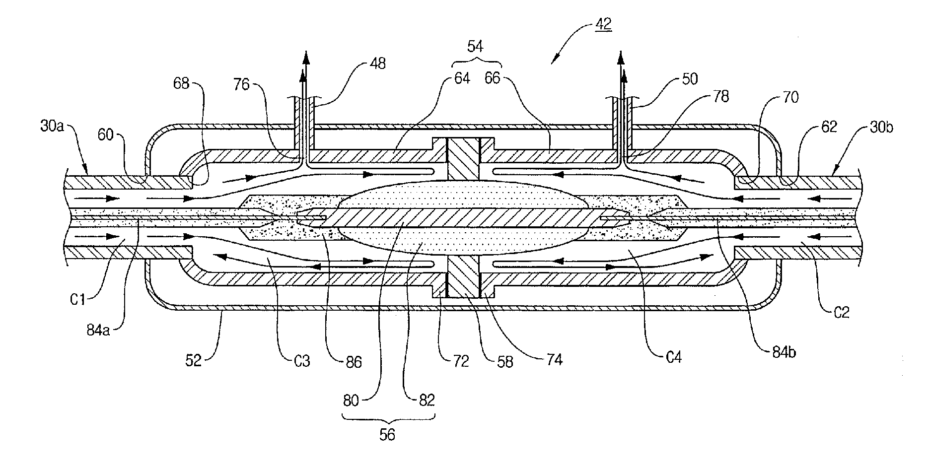
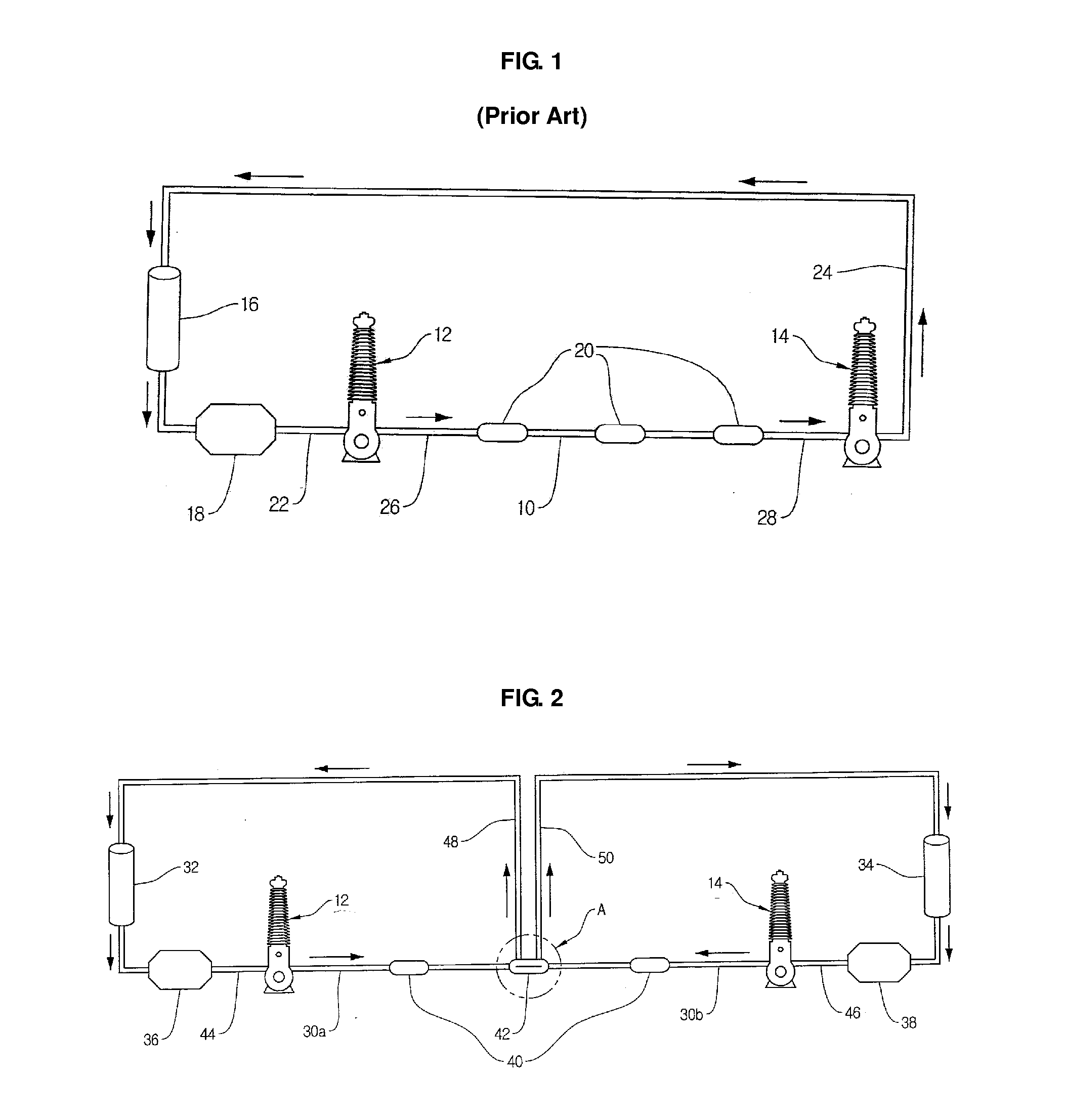
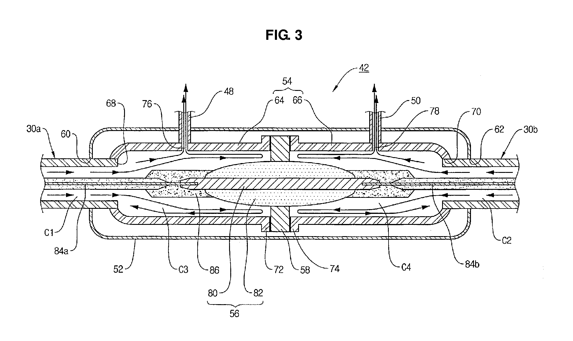
CROSS-REFERENCE TO RELATED APPLICATION[0001]This application claims priority to Korean Patent Application No. 2011-7643, filed on Jan. 26, 2011, and all the benefits accruing therefrom under 35 U.S.C. §119, the contents of which in its entirety are herein incorporated by reference.BACKGROUND[0002]1. Field[0003]This disclosure relates to a stop joint for a superconducting cable, and more particularly, to a stop joint installed on a long distance line (for example, 2 km or longer) in which a long distance superconducting cable has to be installed in order to reduce a circulation distance of a cooling fluid, thereby maintaining superconducting properties.[0004]2. Description of the Related Art[0005]As shown in FIG. 1, a superconducting cable system includes two terminal structures 12 and 14 to which a superconducting cable 10 is connected, and a refrigerator 16 and a circulation pump 18 provided on the front side of the one terminal structure 12.[0006]In addition, in order to extend th...

Claims


Application Information

Patent Timeline
IPC IPC(8): H02G15/24
CPCH01R4/68H02G15/34B01D53/00F25D3/10F25D29/00H01B7/423H01B12/02H01B12/16H01B13/00H10N60/20H10N60/10H10N60/01
Inventor CHOI, CHANG YOULLEE, SU KILJANG, HYUN MANJANG, SEOK HERN
Owner LG CABLE LTD (KR)
Why Eureka
Try Eureka