Relay device and relay method

a relay device and communication packet technology, applied in the field of relay technique of communication packets, can solve the problems of difficult to provide the same number of several million queues corresponding to the number of several million users, unpractical, and remarkable cost increase, so as to save device cost, eliminate uneven distribution of communication packets, and achieve the effect of small cos

Active Publication Date: 2012-07-26
ALAXALA NETWORKS
View PDF5 Cites 28 Cited by
  • Summary
  • Abstract
  • Description
  • Claims
  • Application Information

AI Technical Summary

Benefits of technology

[0009]In order to achieve at least part of the foregoing, the present invention provides various aspects and embodiments described below. According to a first aspect of the invention, there is provided a relay device of relaying a communication packet, which comprises: an input module configured to receive the communication packet as an input; a buffer configured to have a plurality of queues and temporarily accumulated the received communication packet; a sorter configured to sort the received communication packet to one of the plurality of queues, depending on a specific value obtained by a predetermined function that gives an aggregate output from an input which is transfer information regarding transfer of the communication packet; and a band controller configured to control a bandwidth for each of the plurality of queues and output communication packets accumulated in the plurality of queues for transmission of the communication packets. The relay device according to the first aspect distributes the received communication packets into the plurality of queues, based on the transfer information. This allows for isolation of the effect of discarding communication packets with respect to each of the plurality of queues at the time of congestion. This effectively prevents the congestion from affecting the entire traffic and thereby ensures the quality of service. There is no requirement for providing a queue for each flow, so that the capacity of the buffer used for queues can be saved.
[0010]According to a second aspect of the invention, there is provided the relay device according to the first aspect, wherein the transfer information may comprise destination information that is included in header information of the received communication packet and is specified by a destination of the communication packet. The relay device according to the second aspect distributes the received communication packets into the plurality of queues, based on the destination information. This allows for isolation of the effect of discarding communication packets with respect to each of the plurality of queues at the time of congestion. When congestion occurs due to a specific destination, this effectively prevents the congestion from affecting the entire traffic.
[0011]According to a third aspect of the invention, there is provided the relay device according to the first aspect, wherein the input module may have a plurality of physical input ports, and the transfer information may comprise port information capable of identifying a physical input port that has received the communication packet, among the plurality of physical input ports. The relay device according to the third aspect distributes the received communication packets into the plurality of queues, based on the port information. This allows for isolation of the effect of discarding communication packets with respect to each of the plurality of queues at the time of congestion. When congestion occurs due to a specific source, this effectively prevents the congestion from affecting the entire traffic.

Problems solved by technology

The proposed technique of JP H11-346246, however, needs to set a flow for each user or for each service and accordingly has difficulty in dealing with a large number of users or a large number of services.
For example, when flows are to be set for several million users, it is practically hard to provide an identical number of several million queues corresponding to the number of the several million users.
Even when it is possible to provide several million queues, this requires a storage medium of an enormous storage capacity and has extremely heavy load on sorting received communication packets, thus leading to an unpractical, remarkable cost increase.
It is also inefficient to provide queues for all the users including the users of very low activities.
This saves the device cost.

Method used


Image

  • Relay device and relay method
  • Relay device and relay method
  • Relay device and relay method

Examples


first embodiment

A. First Embodiment

[0025]Embodiments of the invention are described, by way of example only, with reference to the accompanying drawings.

A-1. Network Configuration

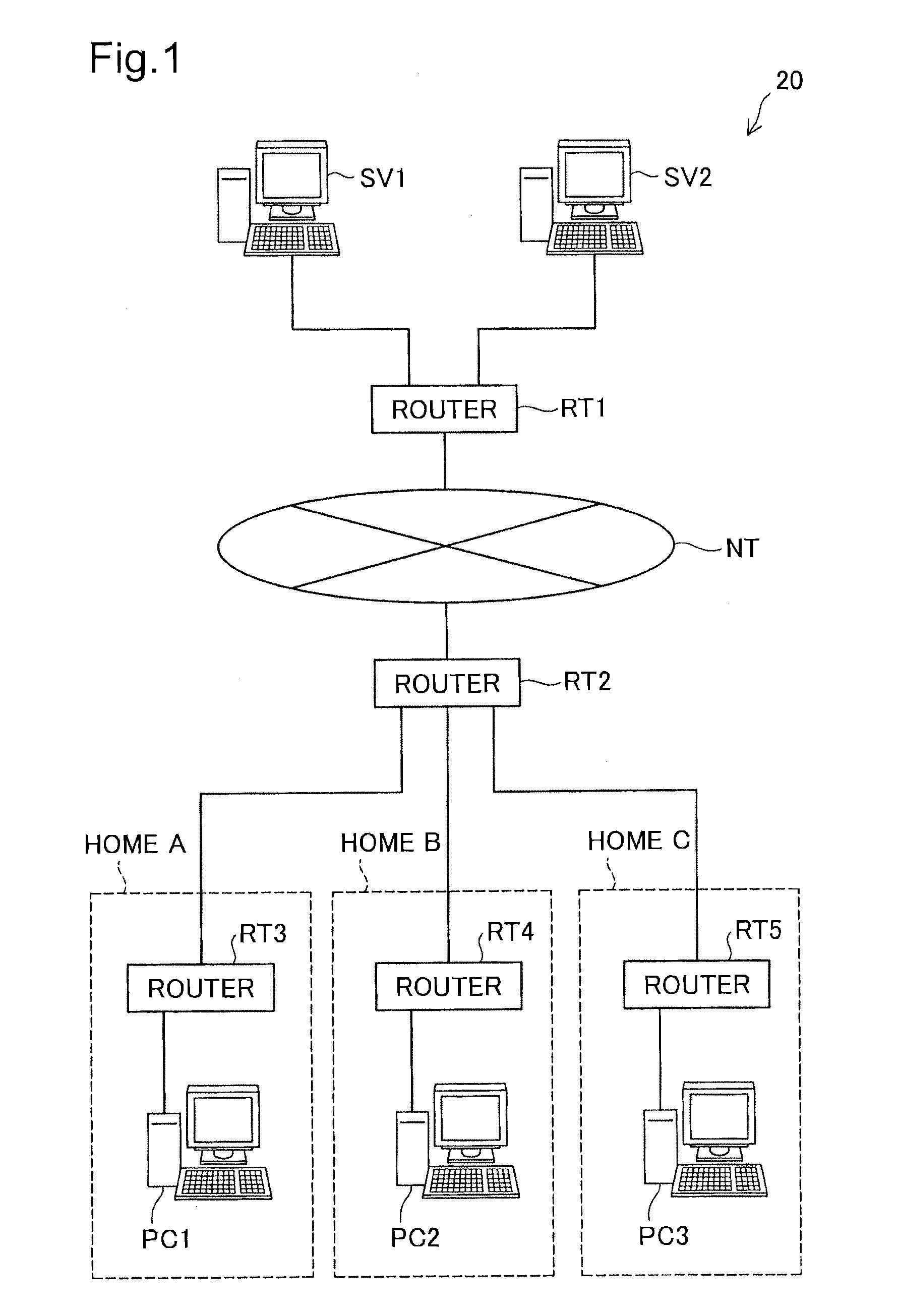
[0026]An exemplary network configuration including routers RT1 and RT2 according to one embodiment of the relay device of the invention is shown in FIG. 1 as a communication system 20. The communication system 20 is constructed as a network system providing the user with contents, such as videos, by streaming. As illustrated, the communication system 20 includes servers SV1 and SV2, routers RT1 to RT5 and personal computers PC1 to PC3.

[0027]The servers SV1 and SV2 store various contents and provide the user with the stored contents. These servers SV1 and SV2 are directly connected to the router RT1. For the convenience of description, the number of servers connected to the router RT1 is two according to the illustrated embodiment. But this number is not restrictive, and three or more servers may be connected to the router ...

second embodiment

B. Second Embodiment

[0049]According to a second embodiment of the invention, a router RT1 sorts communication packets, based on both the destination information and the port information, unlike the first embodiment. Otherwise the system configuration of the second embodiment is identical with that of the first embodiment. The general structure of the router RT1 according to the second embodiment is shown in FIG. 3. The like components shown in FIG. 3 to those of the first embodiment shown in FIG. 2 are expressed by the like symbols and are not specifically described here. Two components of the second embodiment corresponding to one component of the first embodiment are expressed by the like symbol with suffixes “a” and “b” for the purpose of distinction and are only briefly described. As shown in FIG. 3, the router RT1 according to the second embodiment includes an input module 110, sorters 120a and 120b, buffers 130a and 130b, band controllers 140a and 140b, an output module 150, d...

third embodiment

C. Third Embodiment

C-1. Device Structure

[0055]According to a third embodiment of the invention, a router RT1 transfers a communication packet, which is sorted to a queue detected as congestion, to an importance analyzer 190 and changes the discard priority corresponding to the degree of importance of the communication packet. This is the primary difference from the system of the first embodiment, as described in detail below.

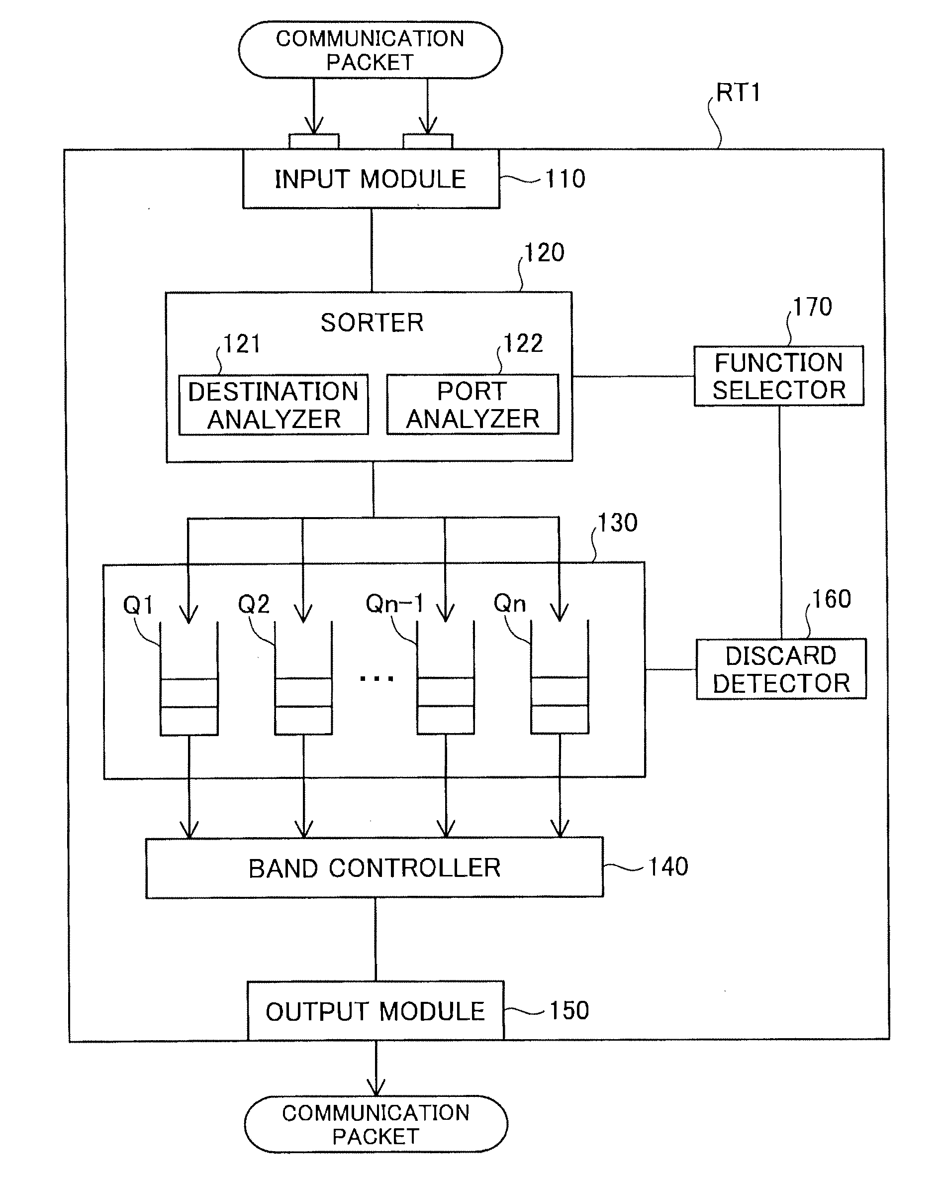
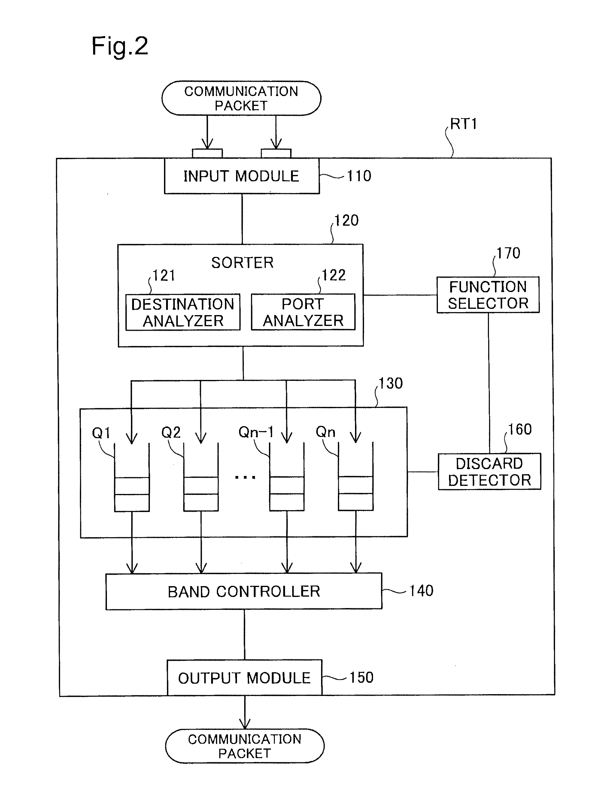
[0056]The general structure of the router RT1 according to the third embodiment is shown in FIG. 4. With reference to FIG. 4, the router RT1 of the third embodiment includes an input module 110, a sorter 120, a buffer 130, a band controller 140, an output module 150, a discard detector 160, a process modifier 180 and an importance analyzer 190. The primary differences from the first embodiment are addition of the process modifier 180 and the importance analyzer 190, as well as series of operations of the sorter 120 and the buffer 130 as described below in detail...


PUM


Abstract

A relay device of relaying a communication packet is disclosed, which comprises: an input module configured to receive the communication packet as an input; a buffer configured to have a plurality of queues and temporarily accumulated the received communication packet; a sorter configured to sort the received communication packet to one of the plurality of queues, depending on a specific value obtained by a predetermined function that gives an aggregate output from an input which is transfer information regarding transfer of the communication packet; and a band controller configured to control a bandwidth for each of the plurality of queues and output communication packets accumulated in the plurality of queues for transmission of the communication packets. This ensures the quality of service, while saving the capacity of the buffer used for the queues.

Description

CROSS REFERENCE TO RELATED APPLICATIONS[0001]This application claims the priority based on Japanese Patent Application No. 2011-13547 filed on Jan. 26, 2011, Japanese Patent Application No. 2011-141383 filed on Jun. 27, 2011 and Japanese Patent Application No. 2011-240766 filed on Nov. 2, 2011, the disclosures of which are hereby incorporated by reference in their entireties.BACKGROUND[0002]1. Technical Field[0003]The present invention relates to relay technique of communication packets and more specifically to transmission bandwidth control.[0004]2. Description of the Related Art[0005]Recently, streaming technology for real-time delivery of electronic contents, such as video or sound, via a network has become popular. Such streaming via the Internet enables a large number of users to share an identical line, so as to save the cost per bandwidth. There is a requirement for reducing the amount of discarded communication packets and ensuring the quality of service (QoS). One proposed ...

Claims


Application Information

Patent Timeline
Patent Type & Authority Applications(United States)
IPC IPC(8): H04L12/26H04L12/56H04L47/20H04L47/41H04L47/6275
CPCH04L47/2441H04L49/9036H04L47/6275H04L47/60
Inventor KUMAGAI, TAKESHIMATSUYAMA, NOBUHITOAIMOTO, TAKESHIDOI, TOSHIOSUGAI, KAZUO
Owner ALAXALA NETWORKS
Why Eureka
Try Eureka