MR Compatible Fluorescence Viewing Device for use in the Bore of an MR Magnet

a fluorescence viewing device and scanner technology, applied in measurement devices, instruments, medical science, etc., can solve the problems of limited microsurgery, poor patient outcome, and inability to effectively perform microsurgery, so as to improve patient outcome, reduce neurological deficit, and increase resection percentage

Inactive Publication Date: 2012-07-26
IMRIS
View PDF4 Cites 8 Cited by
  • Summary
  • Abstract
  • Description
  • Claims
  • Application Information

AI Technical Summary

Benefits of technology

[0137]The advantage of the invention is that it results in increased resection percentage and decreased neurological deficit. It is the combination of intra operative MRI, intra operative fluorescence and the robot which makes this unique and innovative. The aim is always to improve patient outcome and having the imaging technologies essentially simultaneous available when the surgeon (robot) performs the surgery leads to the best result. The fluorescence imaging brings the dimensions almost to the cellular level and the robot is much more accurate than any human surgeon.
[0138]This invention bring together real time imaging at a cellular level of tumor cells with almost real time imaging of the environment of these tumor cells in the human brain at the time when the

Problems solved by technology

A disclosure of procedures within the bore is shown but this is limited to stereotactic procedures using one arm only and is limited by the fact that the microscope disclosed is not suitable for use within the bore thus precluding effective microsurgery.
That is the microsurgery is limited by the availability of a MR compatible stereoscopic microscope device with interactive high resolution to view the surgical site.
In addition, line-of-sight issues exist in the following configuration: patient in the bore of the magnet; in-bore microscope

Method used


Image

  • MR Compatible Fluorescence Viewing Device for use in the Bore of an MR Magnet
  • MR Compatible Fluorescence Viewing Device for use in the Bore of an MR Magnet
  • MR Compatible Fluorescence Viewing Device for use in the Bore of an MR Magnet

Examples


Embodiment Construction

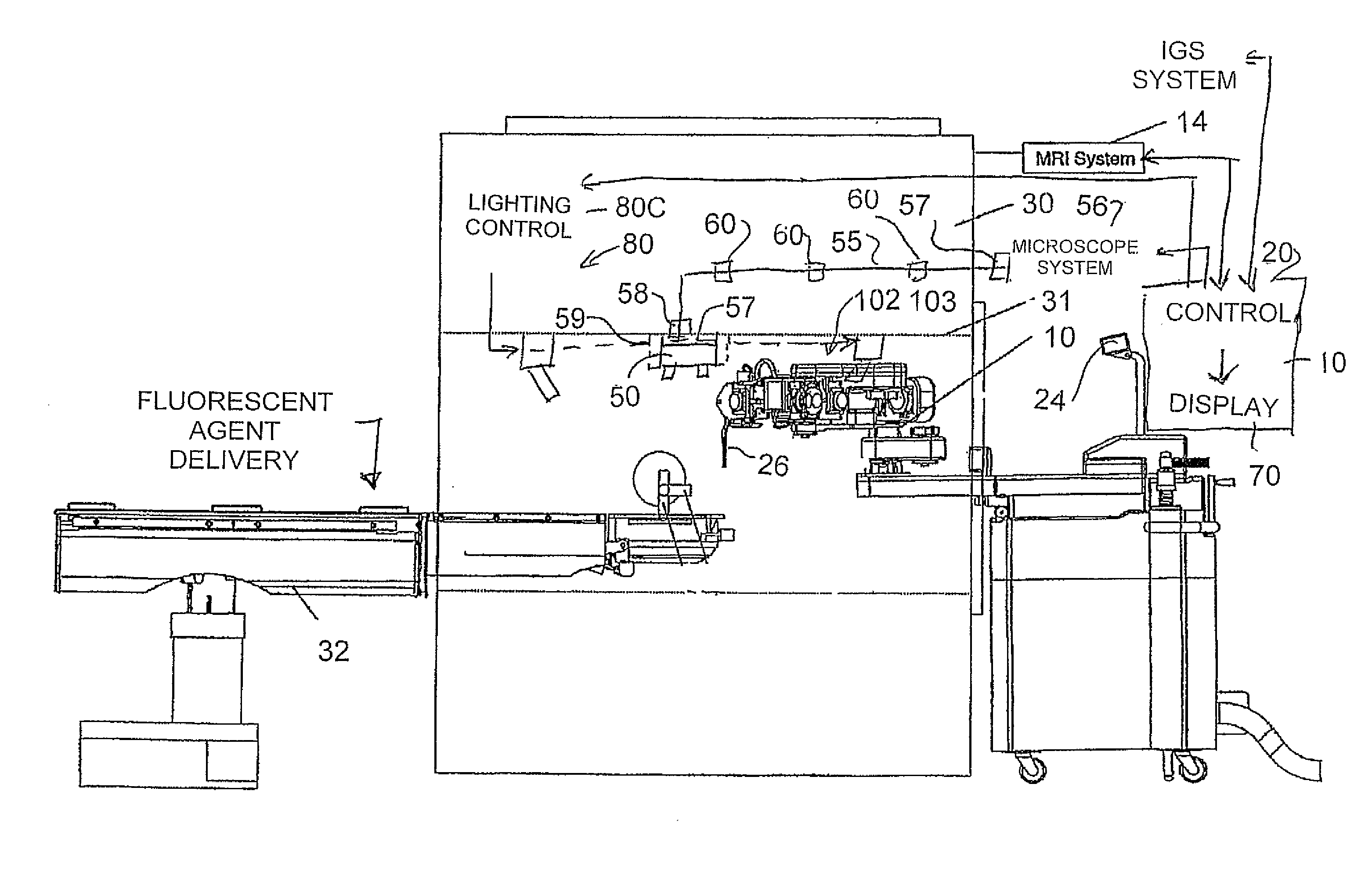
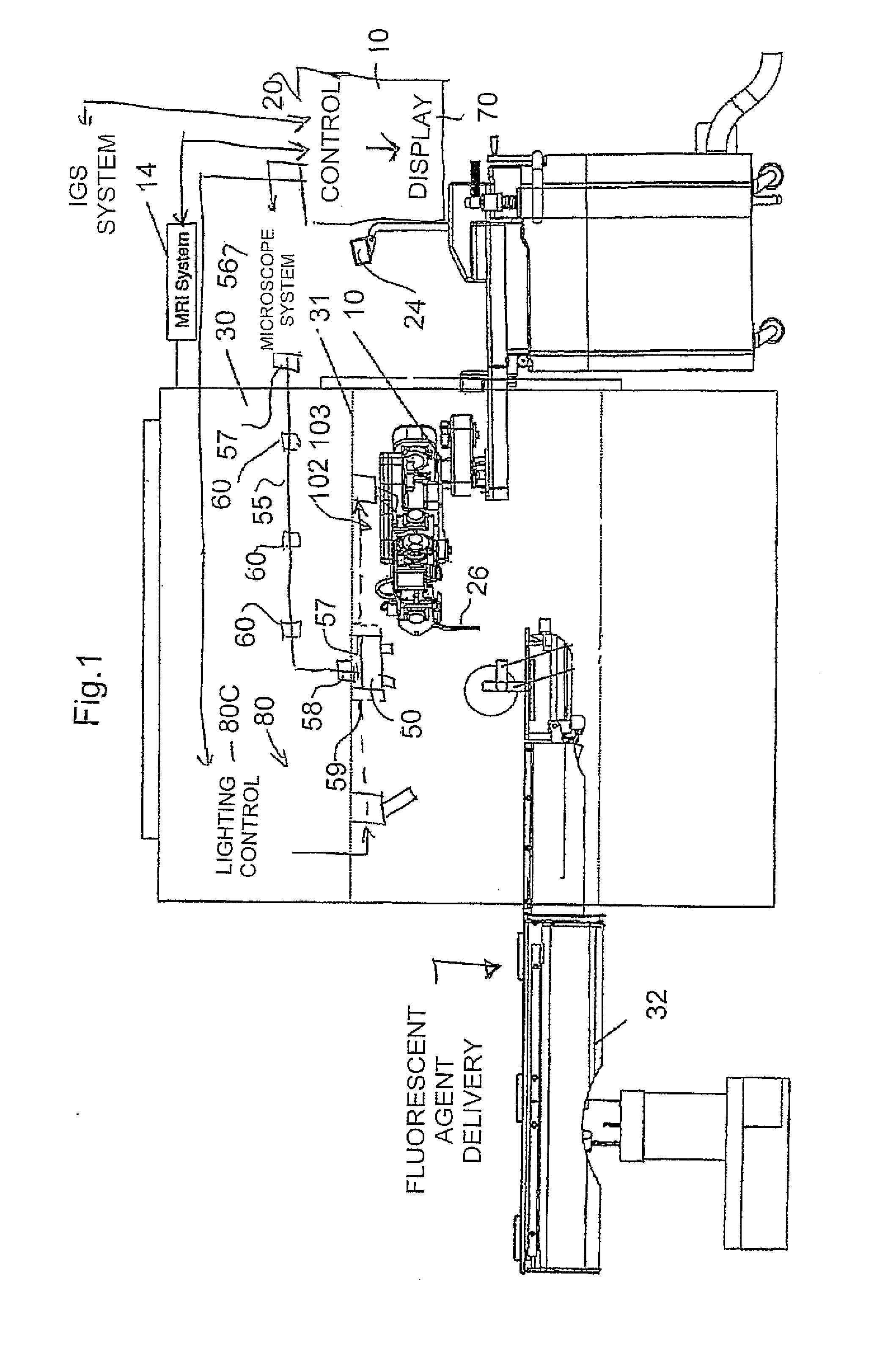
[0147]An overview of the system is shown in FIG. 6 which comprises a robot manipulator 10, a work station 11 and a controller 12 which communicates between the robot manipulator and the work station. As an input to the work station is also provided a stereo microscope 13, an MRI imaging system 14 and a registration system 15.

[0148]The work station includes a number of displays including at first display 16 for the MRI image, a second display 17 for the microscope image and a third display 18 for the system status. Further the work station includes two hand controllers schematically indicated at 19 and an input interface 20 allowing the surgeon to control the systems from the work station while reviewing the displays. The work station further includes a computer or processor 21, a data recording system 22 and a power supply 23.

[0149]The display 17 includes a stereoscopic display 17A which provides a simulated microscope for viewing the images generated by the stereo-microscope system...


PUM


Abstract

In an MR guided surgical system which is carried out in the bore of an MR magnet and uses fluorescence to detect tumor cells, there is provided a microscope system for viewing the required part of a patient which includes stereoscopic viewing components arranged for use in generating 2D and 3D images displayed to the surgeon. The optical assembly is adjustable to change the view and the visual images are overlaid by the MR images. The visual image can be adjusted in response to movement of the surgical tool and the MR image displayed and/or the image obtained can be modified in response to change in the visual image and/or movement of the tool. The components in the bore are made compatible with the MR environment. A fluorescence delivery system is operated to automatically activate the delivery system in response to detection of the level of fluorescence.

Description

[0001]This application is a continuation in part of application Ser. No. 13 / 012,164 filed Jan. 24, 2011.[0002]This invention relates to an MR compatible stereoscopic viewing device for use in the bore of a magnet and to its cooperation with MR images and with a robot surgical system. The system may be used to generate combined fluorescence and MR images for improved surgery guidance in the resection of tumors.BACKGROUND OF THE INVENTION[0003]In U.S. Pat. No. 7,155,316 (Sutherland) issued Dec. 26, 2006 is disclosed a system for Robotic microsurgery within the bore of an MR scanner. The disclosure of this patent is incorporated herein by reference or should be referred to for further details of the MR and robotic surgery system with which the present invention is concerned.[0004]The above patent discloses a microsurgical robot system which is intended for use with an MR imaging system where the imaging magnet is retracted during the operating procedure since the system cannot function...

Claims


Application Information

Patent Timeline
IPC IPC(8): A61B5/055
CPCA61B5/0071A61B5/055G01R33/4808A61B19/2203A61B5/0064A61B19/5225A61B5/0035A61B34/30A61B90/37A61B5/7425
Inventor SCHAERER, SHAWNALEXIUK, MARKSCARTH, GORDSAUNDERS, JOHN K.DAHAN, MEIR
Owner IMRIS
Why Eureka
Try Eureka