Surface mount device and method of manufacturing the same

a surface mount device and manufacturing method technology, applied in the direction of coupling device connection, sustainable manufacturing/processing, semiconductor/solid-state device details, etc., can solve the problems of disconnection of leads to the board, different distance between the board and each of the leads, etc., to achieve good connection and variation in the length of the leads

Inactive Publication Date: 2012-08-02
FUJITSU COMPONENENT LTD
View PDF9 Cites 11 Cited by
  • Summary
  • Abstract
  • Description
  • Claims
  • Application Information

AI Technical Summary

Benefits of technology

[0006]The present invention is made in light of the above problems, and provides a surface mount device and a method of manufacturing the surface mount device which can form a good connection with a base member such as a board or the like even when the base member warps or there is a variation in the length of the leads.
[0008]According to an embodiment, there is provided a surface mount device to be mounted on a base member, including plural lead units, each of the plural lead units including, a lead including a body portion and a foot formed at an end of the lead; a solder portion formed at the foot of the lead to protrude toward the direction of the base member to have a summit portion, and a diffusion prevention portion provided on the lead for preventing a diffusion of a solder along the body portion of the lead.

Problems solved by technology

However, when heating the structure for mounting the connector to the printed circuit board as described in U.S. Pat. No. 6,986,682, the board easily warps so that the distance between the board and each of the leads becomes different and a problem occurs where there is disconnection of the leads to the board occurs.

Method used


Image

  • Surface mount device and method of manufacturing the same
  • Surface mount device and method of manufacturing the same
  • Surface mount device and method of manufacturing the same

Examples


Embodiment Construction

[0039]The invention will be described herein with reference to illustrative embodiments. Those skilled in the art will recognize that many alternative embodiments can be accomplished using the teachings of the present invention and that the invention is not limited to the embodiments illustrated for explanatory purposes.

[0040]Next, embodiments of the present invention will be described below with reference to drawings.

[0041]It is to be noted that, in the explanation of the drawings, the same components are given the same reference numerals, and explanations are not repeated.

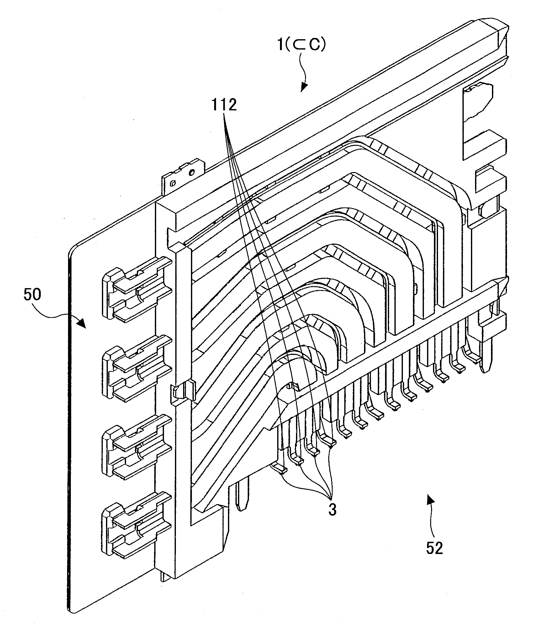
[0042]FIG. 11 is a perspective view showing an example of a connector C of an embodiment. The connector C includes a housing 6 and plural connector modules 1 fixed in the housing 6 and aligned along a width direction. The structure of the connector C will be explained later.

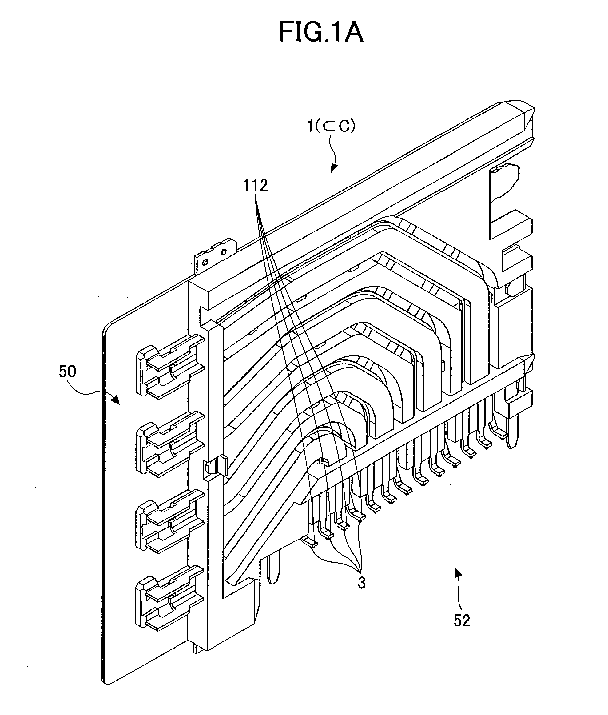
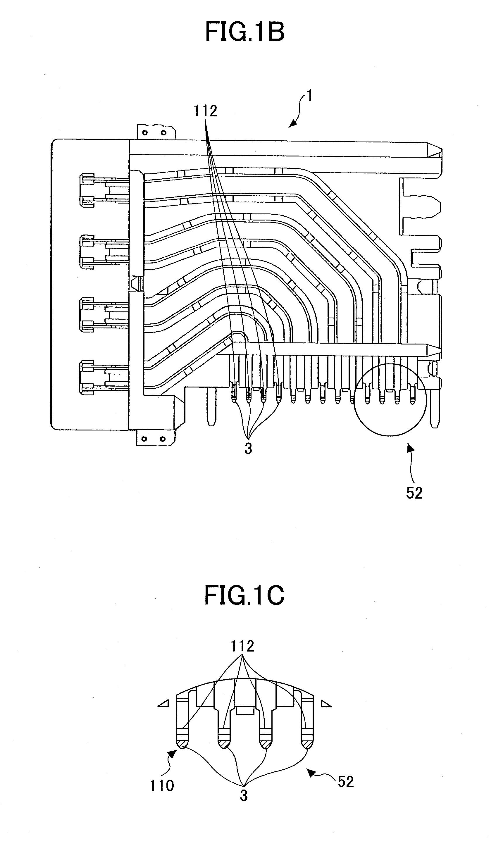
[0043]FIG. 1A is a perspective view showing an example of the connector module 1 included in the connector C of the embodiment. FIG. 1B is a ...


PUM

PropertyMeasurementUnit
angleaaaaaaaaaa
widthaaaaaaaaaa
widthaaaaaaaaaa

Abstract

Disclosed is a surface mount device to be mounted on a base member, including plural lead units, each of the plural lead units including, a lead including a body portion and a foot formed at an end of the lead; a solder portion formed at the foot of the lead to protrude toward the direction of the base member to have a summit portion, and a diffusion prevention portion provided on the lead for preventing a diffusion of a solder along the body portion of the lead.

Description

BACKGROUND OF THE INVENTION[0001]1. Field of the Invention[0002]The present invention relates to a surface mount device which is to be mounted on a base member such as a board and method of manufacturing the surface mount device and more specifically, to a surface mount device including plural leads to be connected to pads or the like of a base member such as a board by solder and a method of manufacturing the surface mount device.[0003]2. Description of the Related Art[0004]For a surface mount device (SMD), including plural leads, to be mounted by a surface mount technology (SMT), the leads are generally formed into L shape, J shape, butt shape, Ball Grid Array (BGA) or the like. U.S. Pat. No. 6,986,682 discloses a high speed connector assembly including surface mount connectors. In such a device, a flexible printed circuit (FPC) portion is attached to a printed circuit board using solder balls.[0005]However, when heating the structure for mounting the connector to the printed circ...

Claims


Application Information

Patent Timeline
Patent Type & Authority Applications(United States)
IPC IPC(8): H05K5/02H05K3/00H01R9/00
CPCH01R4/028H01R12/57H01R12/724H01R13/6587H05K1/025H05K2201/2081H05K2201/10189H05K2201/10757H05K2201/10803H05K2201/10909H05K3/3426Y02P70/50H05K3/3494H05K2203/04
Inventor OKUYAMA, TAKESHIKUSAGAYA, TOSHIHIROYAMAKAMI, TOHRU
Owner FUJITSU COMPONENENT LTD
Why Eureka
Try Eureka