Clamp

a technology of clamping and spherical plate, which is applied in the field of clamping, can solve the problems of glass being prone to damage, glass being fragile and prone to damage, and the clamping b>1/b> cannot be used for glass substrates of different lengths, so as to save production costs and simplify the manufacturing process

a technology of clamping and spherical plate, which is applied in the field of clamping, can solve the problems of glass being prone to damage, glass being fragile and prone to damage, and the clamping b>1/b> cannot be used for glass substrates of different lengths, so as to save production costs and simplify the manufacturing process

US20120193497A1Inactive Publication Date: 2012-08-02DELTA ELECTRONICS JIANGSU +1

Image

  • Clamp
  • Clamp
  • Clamp

Examples


Embodiment Construction

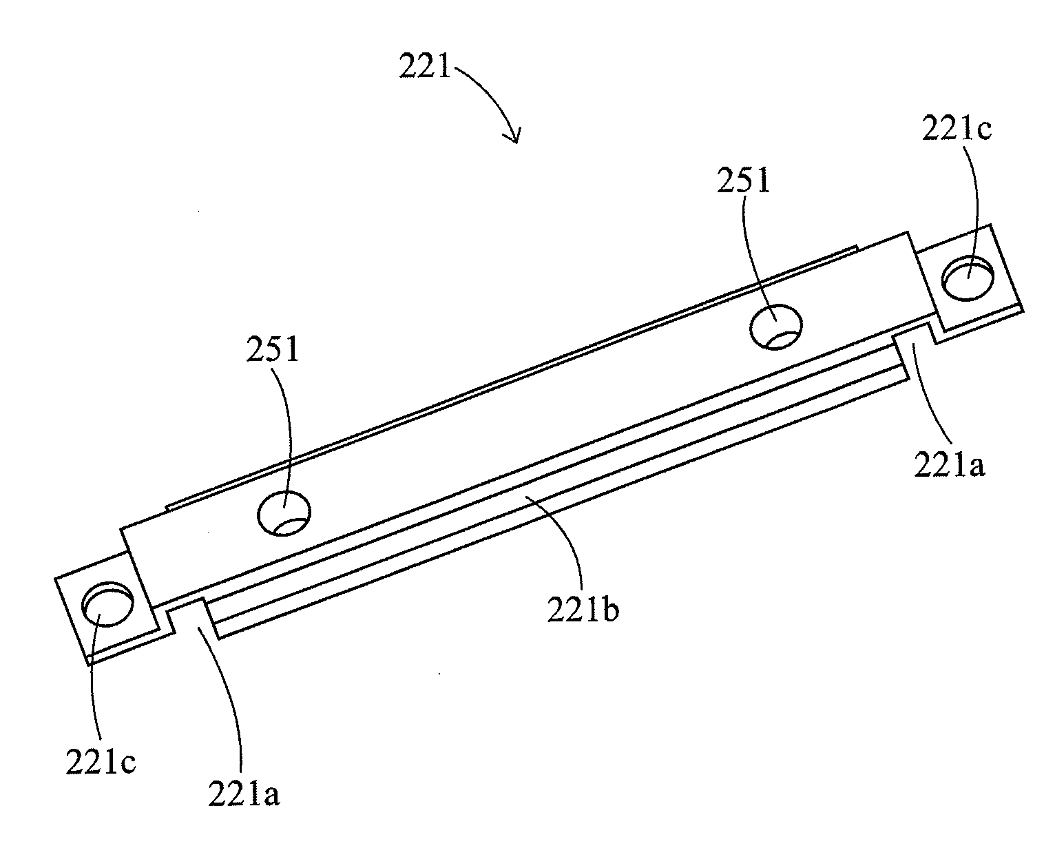
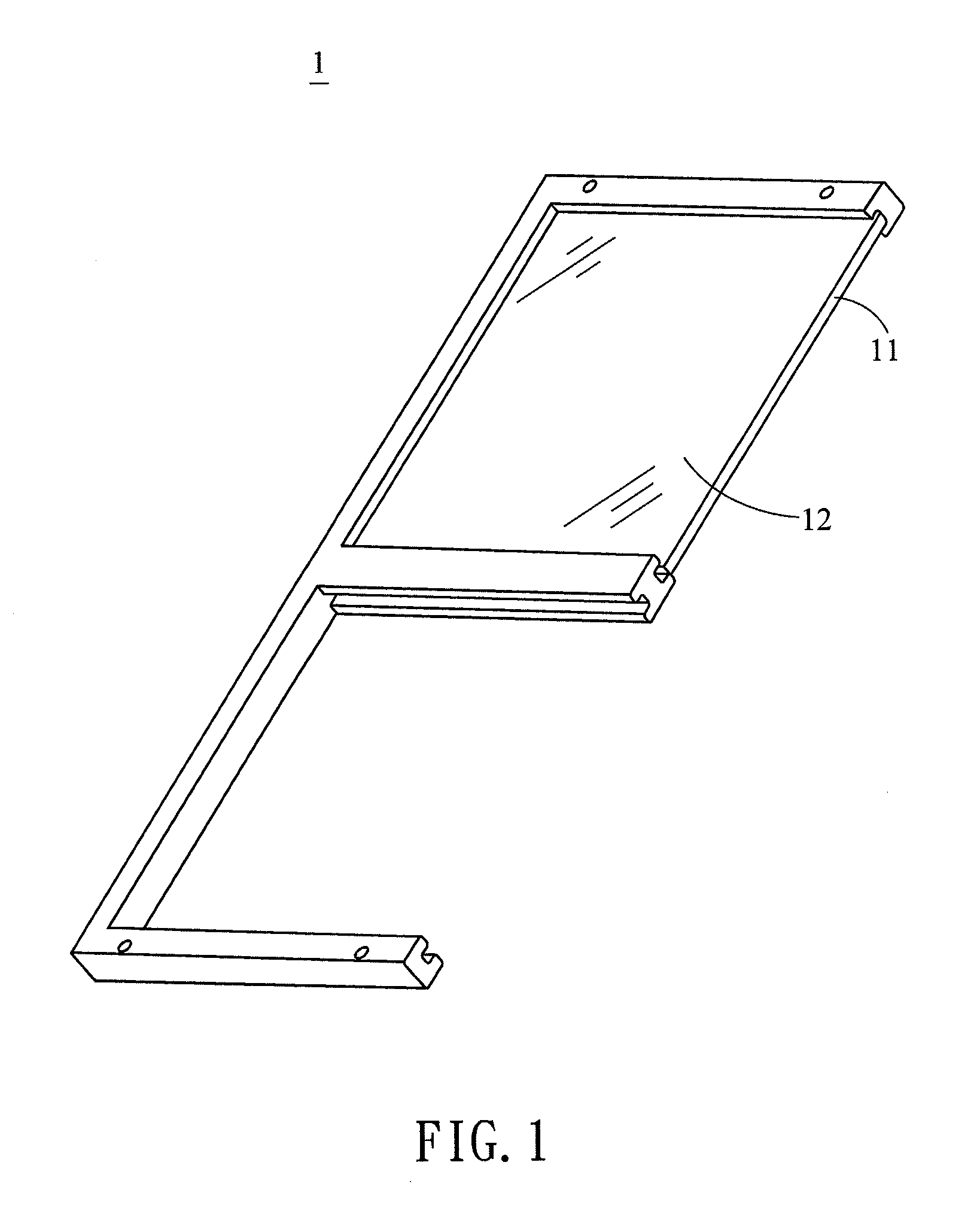
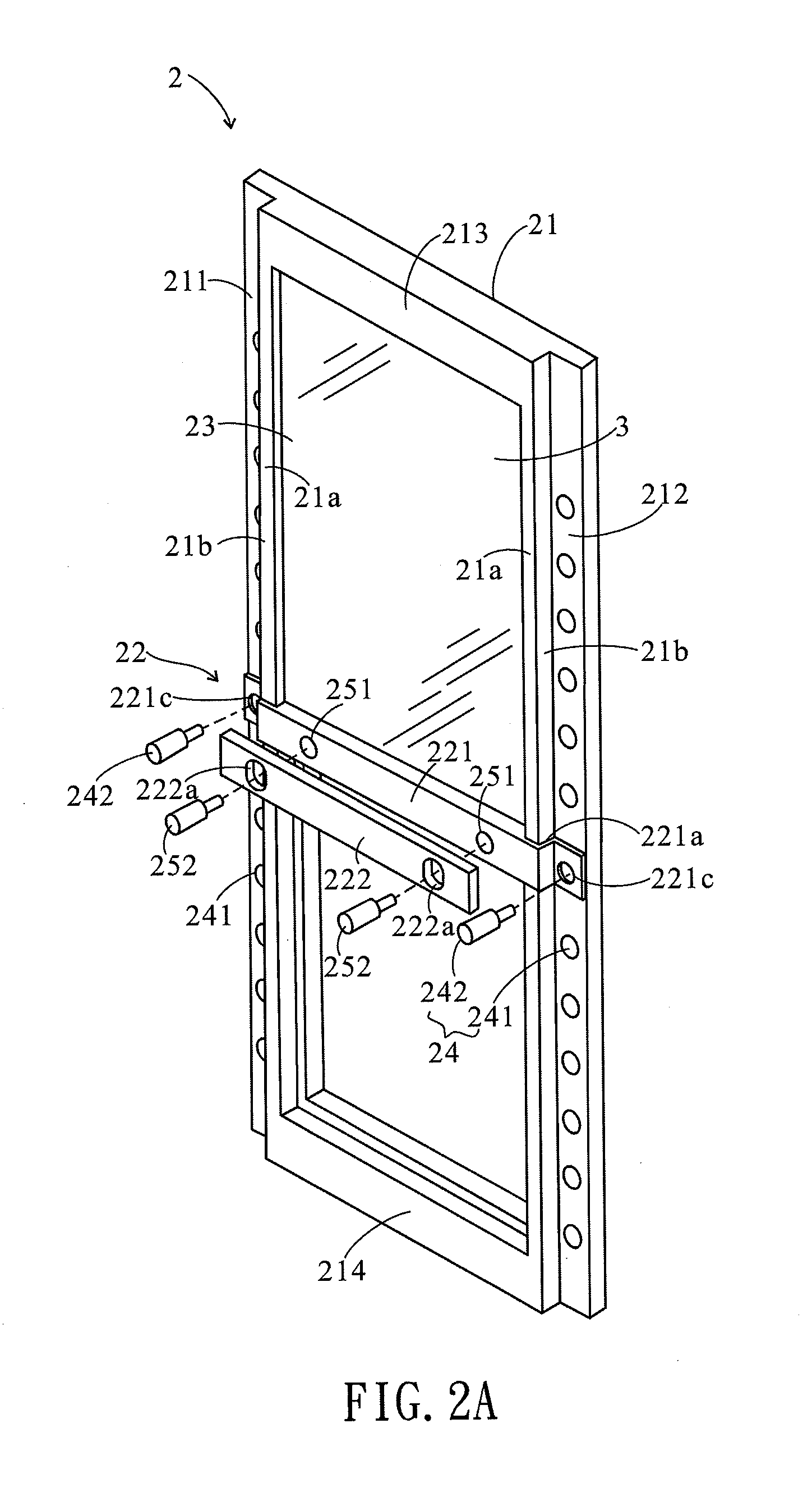
[0019]Accordingly, to protect fragile substrates effectively, the present invention provides a clamp 2. FIG. 2A illustrates a schematic view of a clamp 2 according to an embodiment of the present invention when assembled with a substrate 3. The clamp 2 comprises a frame 21 and a movable structure 22 which is detachably connected with the frame 21 to define a receiving space 23 for receiving at least the substrate 3. The substrate 3 may be a glass substrate. After sliding along a surface 21a of the frame 21 to an appropriate position according to a length of the substrate 3, the movable structure 22 is adapted to partially abut against the substrate 3 and then be fastened together with the frame 21. In this way, an edge of the substrate 3 can be covered completely by the clamp 2 so that when the clamp 2 is further used with other production facilities, a fracture in the substrate 3 due to the impact of the edge of the substrate 3 can be avoided during the related manufacturing proces...


PUM

PropertyMeasurementUnit
depthaaaaaaaaaa
lengthaaaaaaaaaa
widthaaaaaaaaaa

Abstract

A clamp is provided. The clamp comprises a frame and a movable structure. The movable structure is detachably connected with the frame to define a receiving space for receiving at least one substrate. After sliding along a surface of the frame to a suitable position, the movable structure is adapted to be fastened together with the frame to fix the at least one substrate in the receiving space.

Description

[0001]This application claims priority to Chinese Patent Application No. 201110037436.4 filed on Jan. 31, 2011.CROSS-REFERENCES TO RELATED APPLICATIONS[0002]Not applicable.BACKGROUND OF THE INVENTION[0003]1. Field of the Invention[0004]The present invention relates to a clamp, and more particularly, to a clamp whose length can be flexibly adjusted.[0005]2. Descriptions of the Related Art[0006]Over recent years, materials with high light transmissivity such as glass have found wide application in, for example, panels and optical products. However, the glass is fragile and is liable to damage when being impacted, so to reduce the probability of damage to edges of the glass during the manufacturing process, the glass in the form of a substrate is usually fixed by a clamp first before subsequent processes such as film plating, drilling and polishing are performed thereon by using other production facilities.[0007]FIG. 1 illustrates a schematic view of a clamp 1 for fixing a glass substr...

Claims


Application Information

Patent Timeline
02 Aug 2012
Publication
US20120193497A1
IPC
F16B2/12; F16M13/00
CPC
B25B5/14; B25B5/145; B60P3/002; C03B35/202; B65D85/48; C23C14/50; C03B35/20; C03B35/207
Inventors
LAI, TU-FU; ZHU, ZHON GREN