
RF-MEMS Capacitive Switches With High Reliability

a capacitive switch and radio frequency technology, applied in relays, pulse techniques, instruments, etc., can solve problems such as permanent failure of switches and systems, and achieve the effect of reliable, effective and efficien

Inactive Publication Date: 2012-08-02
UCHICAGO ARGONNE LLC
View PDF1 Cites 10 Cited by
  • Summary
  • Abstract
  • Description
  • Claims
  • Application Information

AI Technical Summary

Benefits of technology

[0014]An improved RF-MEMS capacitive switch is provided for controlling, routing, and tuning RF wireless circuits and systems, as well as for other uses and applications. The improved RF-MEMS capacitive switch is reliable, effective and efficient.
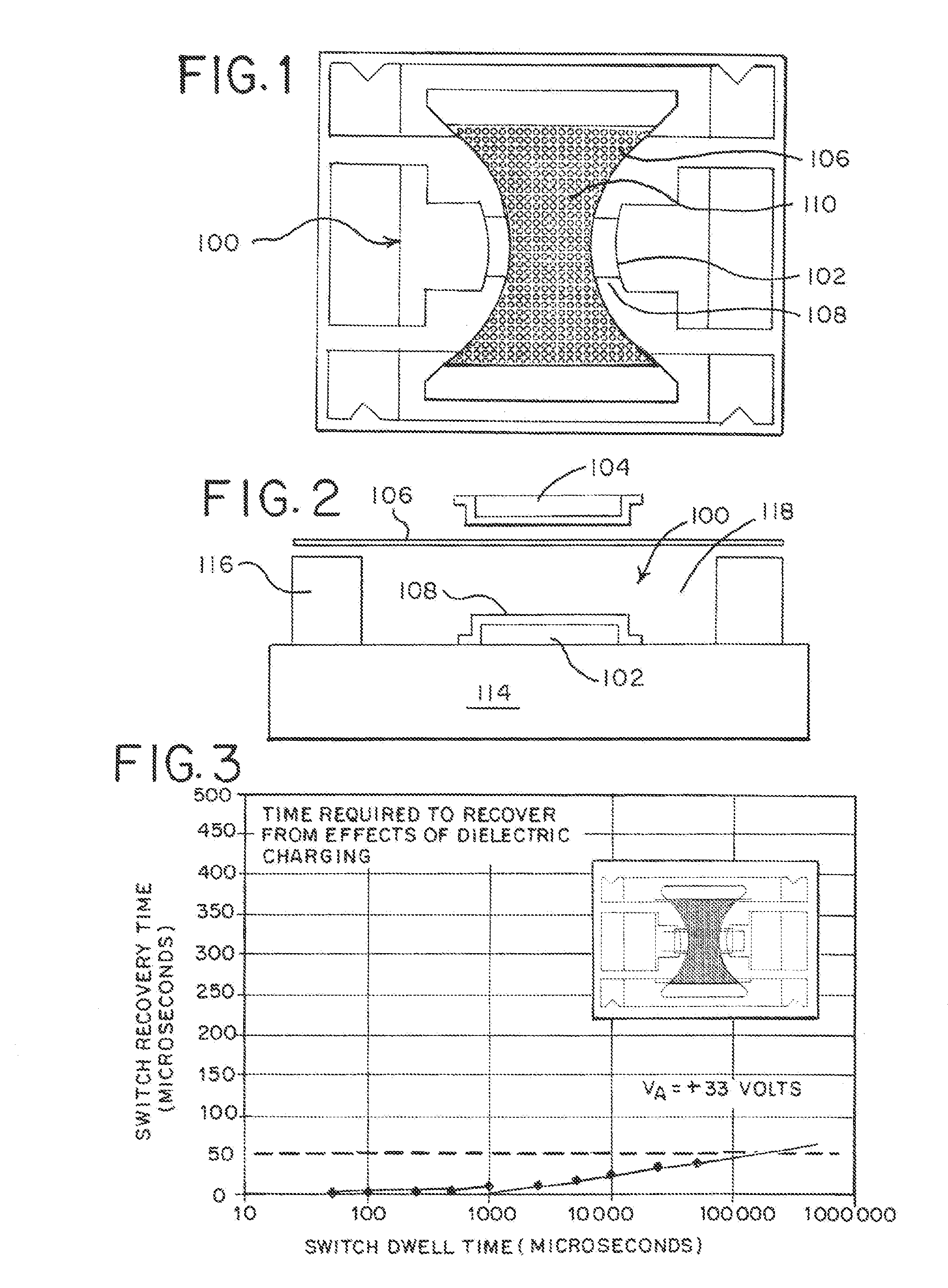
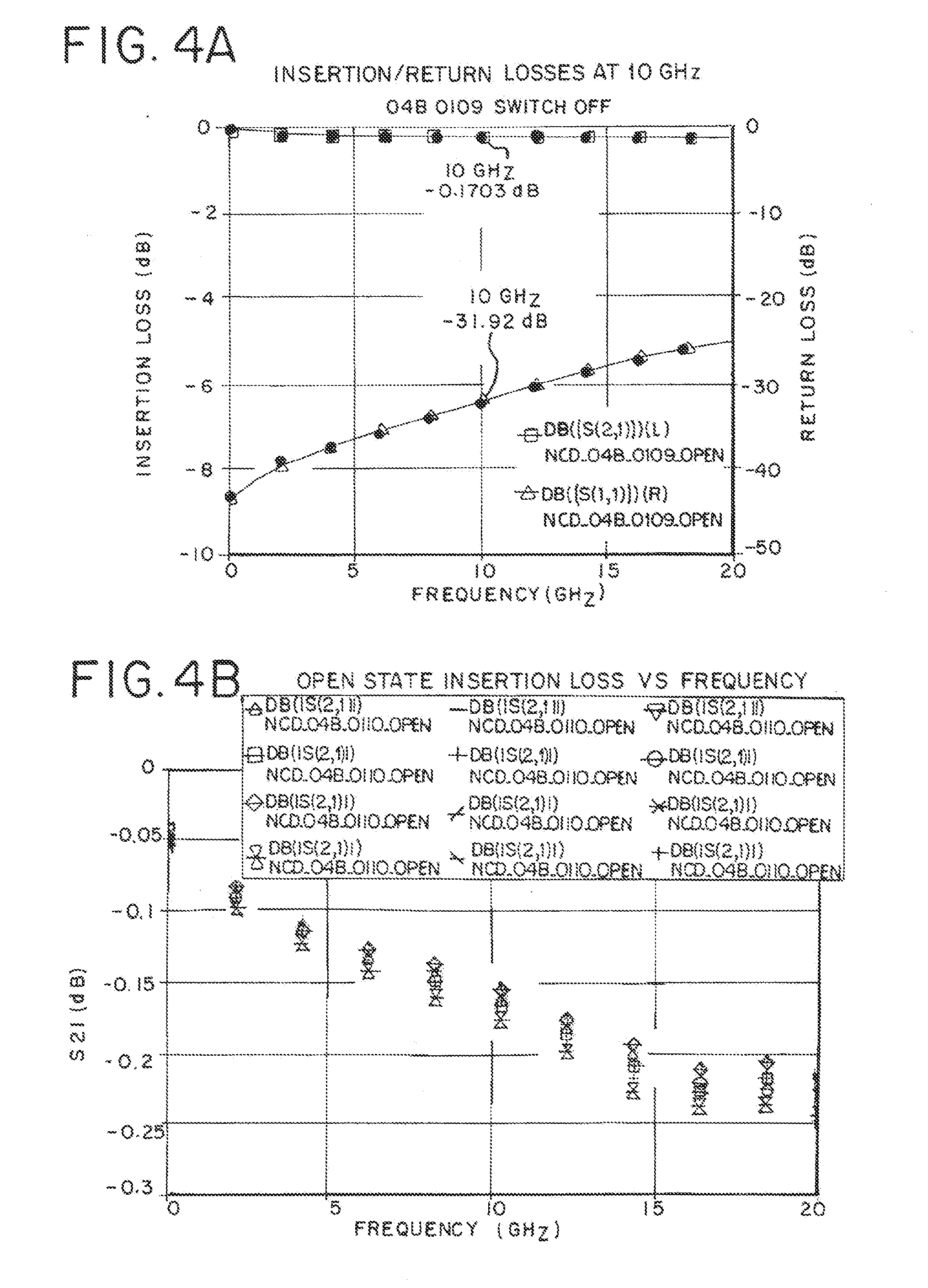
[0015]RF-MEMS capacitive switches can be fabricated with an insulating layer, which comprises a dielectric film that is positioned on top of the bottom electrode. Significantly, in this invention, the dielectric film exhibits a unique nanostructure that provides control of the charging phenomenon via fast transport of injected charges through the grain boundaries of the structure of the material (“fast discharge dielectric layer”) providing an efficient way to control the charge build up in the material, bleeding the charges out of the material with a time constant in the microsecond range, thus enabling reliable, long-life (≧100 billion cycles) operation of the RF-MEMS capacitive switches. In this invention, the material used as a “fast discharge dielectric layer” is diamond in any of the microstructures available in thin films, namely: 1) ultrananocrystalline diamond (UNCD) (with grain size in the 2-5 nm range and gain boundaries about 0.4 nm wide), previously patented by Argonne National Laboratory; 2) nanocrystalline diamond (NCD) (with grain size in the range 10-900 nm), and 3) microcrystalline diamond (MCD) (with grain size in the range ≧1 micron). The term “fast discharge diamond dielectric layer” is used heretofore in the description of the invention, when referring to the dielectric layer. Desirably, the “fast discharge diamond dielectric layer” has sufficiently short discharging time constant that no matter how many charges are accumulated in the material, the RF-MEMS capacitive switch will recover quickly enough so as to be available for proper operation within a relatively short time span (microseconds to tens or hundreds of microseconds).

Problems solved by technology

However, once failure occurs, the recovery time for the switch to be operational again is very long, essentially resulting in permanent failure of the switch and the system in which it is inserted as a critical component.

Method used


Image

  • RF-MEMS Capacitive Switches With High Reliability
  • RF-MEMS Capacitive Switches With High Reliability
  • RF-MEMS Capacitive Switches With High Reliability

Examples


Embodiment Construction

[0039]The following is a detailed description and explanation of the preferred embodiments of the invention and best modes for practicing the invention.

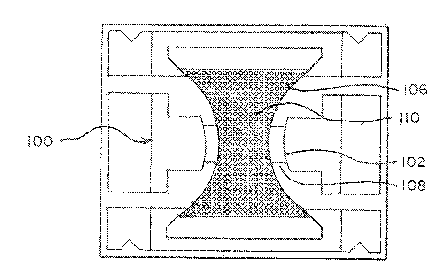
[0040]Referring to the drawings, one embodiment of a RF-MEMS capacitive switch (FIGS. 1 and 2) features a moveable metallic membrane 100 from an “off” position in an “off-state” (no applied voltage) to an “on” position in an “on-state” (with applied voltage), in a short switching time. The RF-MEMS capacitive switch can have: 1) a bottom electrode 101 which provides a lower electrode and comprises a metal that provides a RF signal path 102; a moveable metallic membrane 100 (upper electrode) with large array of holes (103) to enable etching of the sacrificial layer underneath the membrane, during switch fabrication, (alternatively, the switch design could incorporate a pull-up upper electrode, also with a diamond layer, above the membrane (104); 3) a “fast discharge diamond dielectric layer”105, with fast discharge characteristics, and...


PUM


Abstract

A reliable long life RF-MEMS capacitive switch is provided with a dielectric layer comprising a “fast discharge diamond dielectric layer” and enabling rapid switch recovery, dielectric layer charging and discharging that is efficient and effective to enable RF-MEMS switch operation to greater than or equal to 100 billion cycles.

Description

STATEMENT REGARDING FEDERALLY SPONSORED RESEARCH OR DEVELOPMENT[0001]The United States Government has rights in this invention pursuant to Contract No. DE-EG02-02ER46016 between the U.S. Department of Energy (DOE) and UChicago Argonne, LLC representing Argonne National Laboratory and pursuant to Contract No. MIPR06-W238 between the Defense Advanced Research Projects Agency (DARPA) and UChicago Argonne, LLC representing Argonne National Laboratory.BACKGROUND OF THE INVENTION[0002]This invention relates to electrostatically operated microelectromechanical systems (MEMS) devices involving integrated dielectric layers, particularly capacitive switches and more particularly, to radio frequency (RF) microelectromechanical systems (MEMS) capacitive switches.[0003]RF-MEMS capacitive switches have many useful applications for military and commercial RF and microwave applications. A RF-MEMS capacitive switch comprises a movable metal membrane (upper electrode) suspended above a lower electrod...

Claims


Application Information

Patent Timeline
IPC IPC(8): H01L27/20H03K17/975B82Y15/00
CPCH03K17/975H01H59/0009
Inventor GOLDSMITH, CHARLES L.AUCIELLO, ORLANDO H.CARLISLE, JOHN A.SAMPATH, SURESHSUMANT, ANIRUDHA V.CARPICK, ROBERT W.HWANG, JAMESMANCINI, DERRICK C.GUDEMAN, CHRIS
Owner UCHICAGO ARGONNE LLC
Learn More