Contactless power transmission device

Active Publication Date: 2012-08-02
HONDA MOTOR CO LTD
View PDF14 Cites 12 Cited by
  • Summary
  • Abstract
  • Description
  • Claims
  • Application Information

AI Technical Summary

Benefits of technology

[0023]Through the above-described configuration, it is possible to obtain the magnetic field shielding effect in a low frequency band and also to reduce the atten

Problems solved by technology

However, when transmitting electric power in order to charge a radio communication device using a contactless power transmission device mounted in a vehicle, some of the AC power of a frequency used for power transmission or a harmonic or subharmonic of the AC power becomes an electromagnetic wave, an alternating magnetic field, or an alternating electric field and is input as a noise to a neighborin

Method used


Image

  • Contactless power transmission device
  • Contactless power transmission device
  • Contactless power transmission device

Examples


first embodiment

[0029]First, a contactless power transmission device according to a first embodiment of the invention will be described with reference to FIGS. 1 to 3.

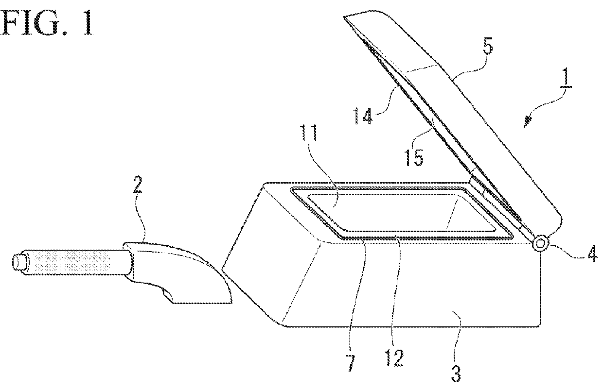
[0030]FIG. 1 is a perspective view showing the appearance of a console box 1 and a parking brake 2 provided between the driver's seat and the passenger seat of a vehicle. In the present embodiment, a contactless power transmission device is provided in the console box 1.

[0031]The console box 1 is provided behind the parking brake 2 in the vehicle and is configured to include a box body 3, which is formed of resin and is fixed to the vehicle body, and a lid 5, which is formed of resin and is fixed so as to be able to be opened and closed in the vertical direction through a hinge 4 provided at the back side of the box body 3.

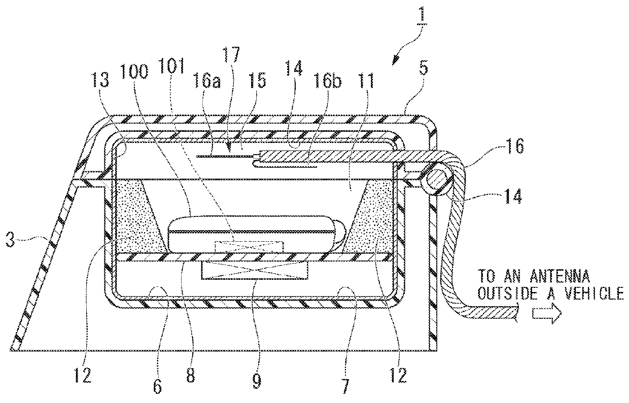
[0032]As shown in FIG. 2, a recess 6 which is open upward is formed in the box body 3, and a shield body 7 (shield structure) which can shield an electromagnetic wave is fixed to the entire inside surface of the rec...

second embodiment

[0059]Next, a contactless power transmission device according to a second embodiment of the invention will be described with reference to FIG. 4.

[0060]The contactless power transmission device according to the second embodiment is also provided in the console box 1 of the vehicle as in the first embodiment.

[0061]The only different point of the contactless power transmission device according to the second embodiment and the contactless power transmission device according to the first embodiment is a form of the external antenna of the coaxial cable 16.

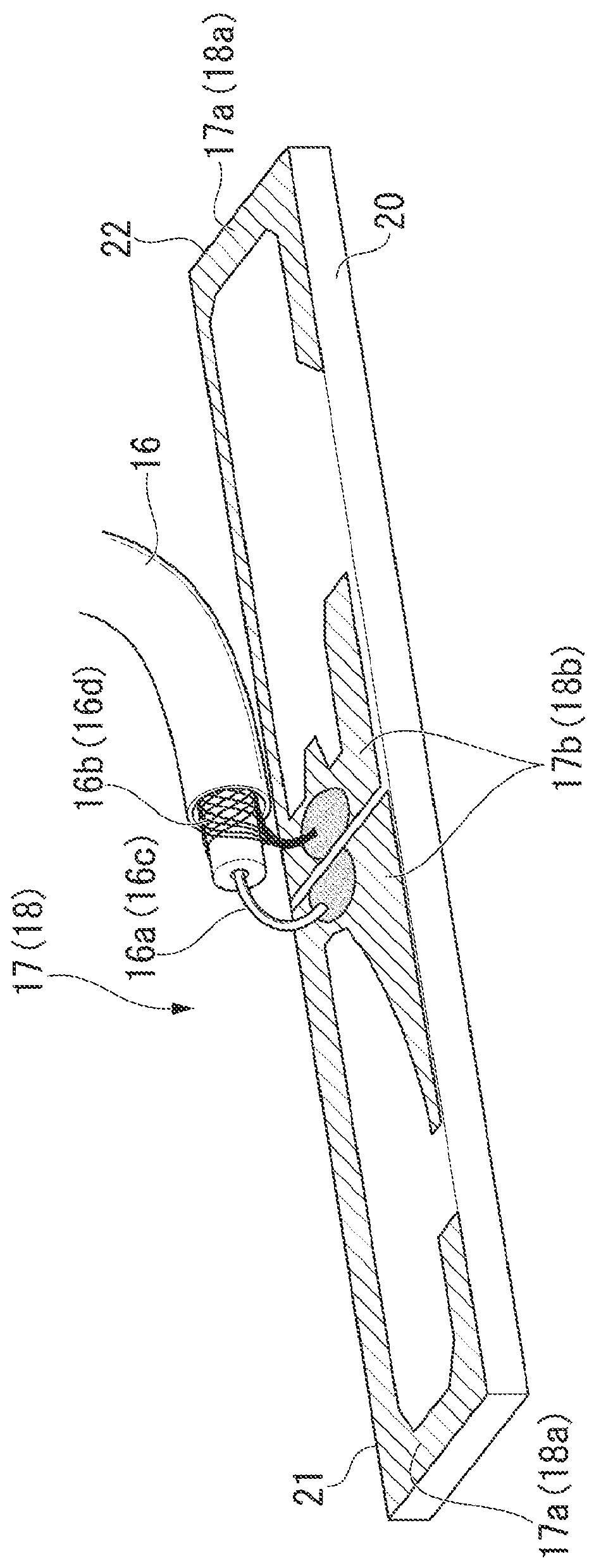
[0062]Also in the second embodiment, the coaxial cable 16 is fixed so as to pass through the shield body 14 and also pass through the inside and the outside of the lid 5, and one end of the coaxial cable 16 is inserted in the housing space 15 of the lid 5 and is connected to the internal antenna 17 in the housing space 15, as in the first embodiment.

[0063]On the other hand, in the second embodiment, the coaxial cable 16 passes through a...


PUM


Abstract

A contactless power transmission device which transmits electric power in a contactless way includes: a power transmission section which transmits electric power using a primary coil; a power receiving section which is provided in a radio communication device and receives electric power using a secondary coil that is electromagnetically coupled with the primary coil; a housing which shields an electromagnetic wave, in which the power transmission section is provided, and which forms a closed space where the radio communication device is housed; and a housing antenna section which is provided in the housing and transmits a first communication signal to the outside of the housing, or transmits a second communication signal to the inside of the housing, the first communication signal being emitted from the radio communication device housed inside the housing, the second communication signal being emitted from the radio communication device housed outside the housing.

Description

BACKGROUND OF THE INVENTION[0001]1. Field of the Invention[0002]The present invention relates to a contactless power transmission device.[0003]Priority is claimed on Japanese Patent Application No. 2011-019443, filed Feb. 1, 2011, and Japanese Patent Application No. 2011-245707, filed Nov. 9, 2011, the content of which is incorporated herein by reference.[0004]2. Description of Related Art[0005]As a charging device for radio communication apparatuses, such as mobile phones, a contactless power transmission device is known.[0006]The contactless power transmission device transmits AC power of a certain frequency from a power transmission device to a power receiving device, which is provided or fixed to a radio communication device, using electromagnetic induction or the like.[0007]For example, U.S Patent Application Publication No. 2008 / 0001572 discloses a contactless power transmission device mounted in a vehicle.[0008]However, when transmitting electric power in order to charge a ra...

Claims


Application Information

Patent Timeline
IPC IPC(8): H02J17/00H02J7/00
CPCH02J17/00H02J50/10H02J50/90H02J50/70H02J7/00716
Inventor KANASUGI, KATSUMIMISHIO, YOSHIHIROKANAHARA, HIROKAZU
Owner HONDA MOTOR CO LTD
Why Eureka
Try Eureka